Cutting machine

a cutting machine and cutting blade technology, applied in the field of cutting machines, can solve the problems of deteriorating cutting precision and increasing the manufacturing cost of the machine, and achieve the effect of improving cutting precision and increasing manufacturing cos

Active Publication Date: 2009-01-13
BUFFALO MACHINERY +1
View PDF3 Cites 25 Cited by
  • Summary
  • Abstract
  • Description
  • Claims
  • Application Information

AI Technical Summary

Benefits of technology

[0006]Therefore, an object of the present invention is to provide a cutting...

Problems solved by technology

As such, manufacturing cost thereof is increased and...

Method used


Image

  • Cutting machine
  • Cutting machine
  • Cutting machine

Examples


Embodiment Construction

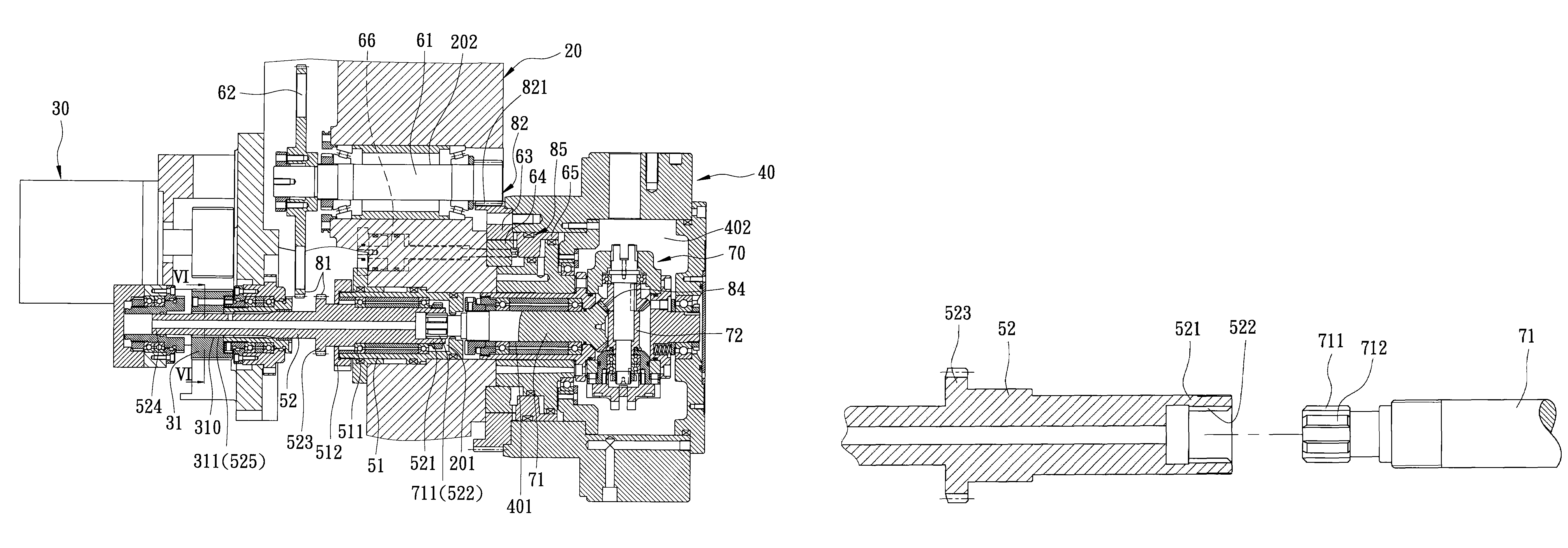
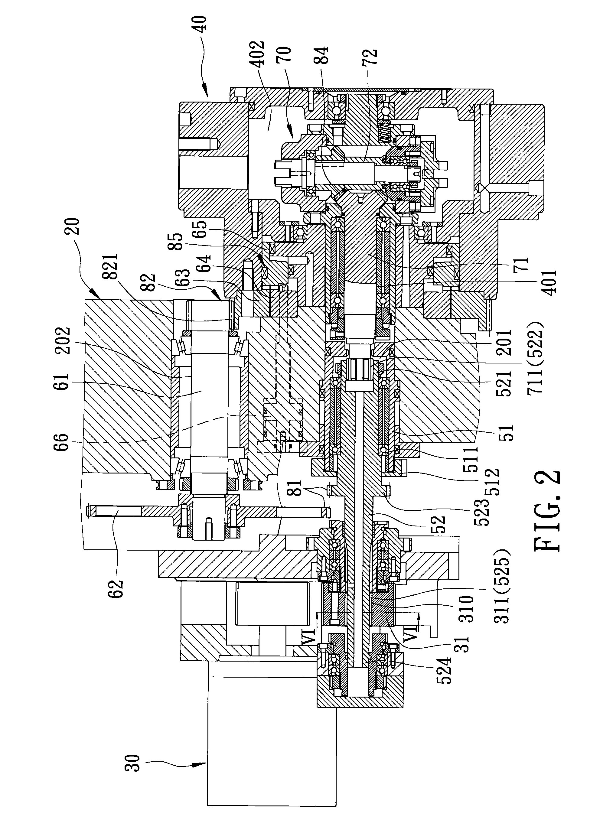
[0015]Referring to FIGS. 2 to 6, the preferred embodiment of a cutting machine according to the present invention is shown to include: a machine body 20 defining parallel first and second cylindrical holes 201, 202; a hollow piston 51 extending into the first cylindrical hole 201 and movable along a first axis defined by the first cylindrical hole 201; a first shaft 52 extending into the piston 51, co-movable with the piston 51 relative to the machine body 20 along the first axis between first and second axial positions (see FIGS. 5 and 2), and rotatable about the first axis relative to the piston 51, the first shaft 52 having a splined end portion 521, and a driven end portion 524 opposite to the splined end portion 521; a first coupling unit 81; a second shaft 61 extending into the second cylindrical hole 202 and rotatable relative to the machine body 20 about a second axis defined by the second cylindrical hole 202 and parallel to the first axis, the first shaft 52 being coupled ...


PUM


Abstract

A cutting machine includes: a machine body; a hollow piston; a first shaft extending into the piston, co-movable with the piston relative to the machine body along a first axis, and rotatable about the first axis relative to the piston; a second shaft rotatable about a second axis and coupled to the first shaft when the first shaft is disposed at a first axial position; a rotary cutter holder rotatable about the first axis and coupled to the second shaft; a third shaft rotatable about the first axis and coupled to the first shaft when the first shaft is disposed at a second axial position; and a driving unit for driving rotation of the first shaft about the first axis.

Description

BACKGROUND OF THE INVENTION[0001]1. Field of the Invention[0002]The invention relates to a cutting machine, more particularly to a cutting machine including a splined shaft rotatable about an axis and movable along the axis for switching to different operations.[0003]2. Description of the Related Art[0004]Referring to FIG. 1, a conventional cutting machine 10 is shown to include a machine body 11, a driving unit 12 mounted on the machine body 11, a first piston unit 13 mounted on the machine body 11 and movable along a first axis defined by the first piston unit 13, and a rotary cutter holder 14 mounted rotatably on an outer side of the machine body 11. The cutting machine 10 further includes a first shaft 111 mounted in the machine body 11. The first shaft 111 has one end provided with a shaft gear 1112 meshing with a driving gear 121 of the driving unit 12 for power transmission, and an opposite end extending into the first piston unit 13 and formed with a male spline gear 1111. T...

Claims


Application Information

Patent Timeline
IPC IPC(8): B23B29/32B23B39/20
CPCB23Q5/04B23Q16/025Y10T74/14Y10T29/5155Y10T29/5165B23Q2220/002
Inventor CHANG, PAULCHEN, TSAIR-RONGROW, JEEN-SHEENTSAI, YUAN-FU
Owner BUFFALO MACHINERY
Why Eureka
Try Eureka