Capacitance-based fluid level sensor

a technology of capacitance and fluid level sensor, which is applied in the direction of liquid/fluent solid measurement, instruments, machines/engines, etc., can solve the problems of reducing the reliability or even complete inoperability of a float-type fluid level sensor, affecting the use of float-type sensors, and agitating the fluid in the monitored spa

Inactive Publication Date: 2009-01-13
WACKER NEUSON PRODN AMERICAS
View PDF25 Cites 3 Cited by
  • Summary
  • Abstract
  • Description
  • Claims
  • Application Information

AI Technical Summary

Problems solved by technology

Some applications, however, are ill-suited for float-type sensors.
For instance, some machines are subject to severe vibrations or dramatic changes in orientation in use, resulting in significant agitation of the fluid within the monitored space as well as jostling of the float.
These events result in reduced reliability or even complete inoperability of a float-type fluid level sensor.
Electronic fluid level sensors have been proposed and even implemented that lack the disadvantages of float-type sensors, but prior known electronic fluid level sensors have problems of their own.

Method used


Image

  • Capacitance-based fluid level sensor
  • Capacitance-based fluid level sensor
  • Capacitance-based fluid level sensor

Examples


first embodiment

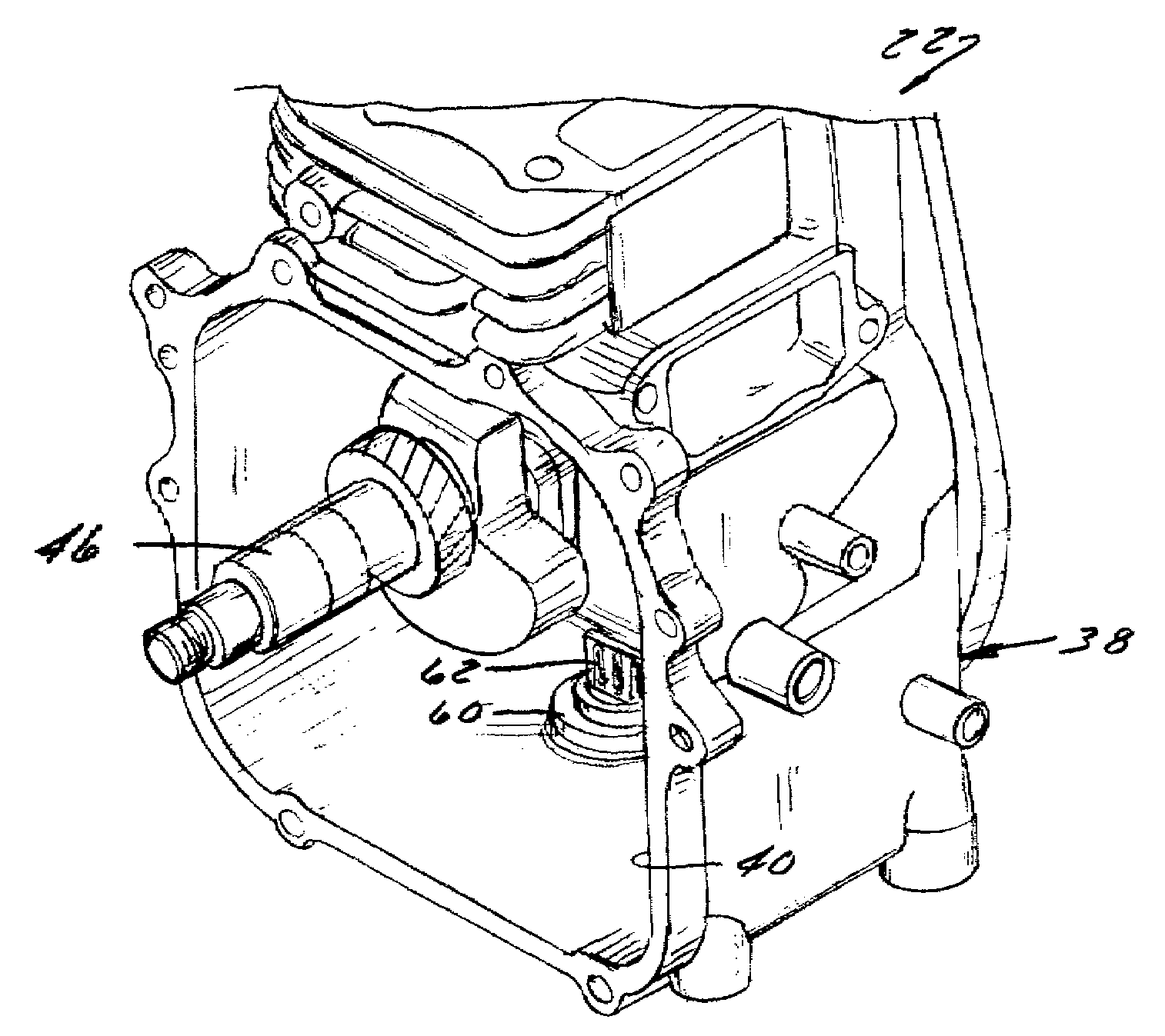
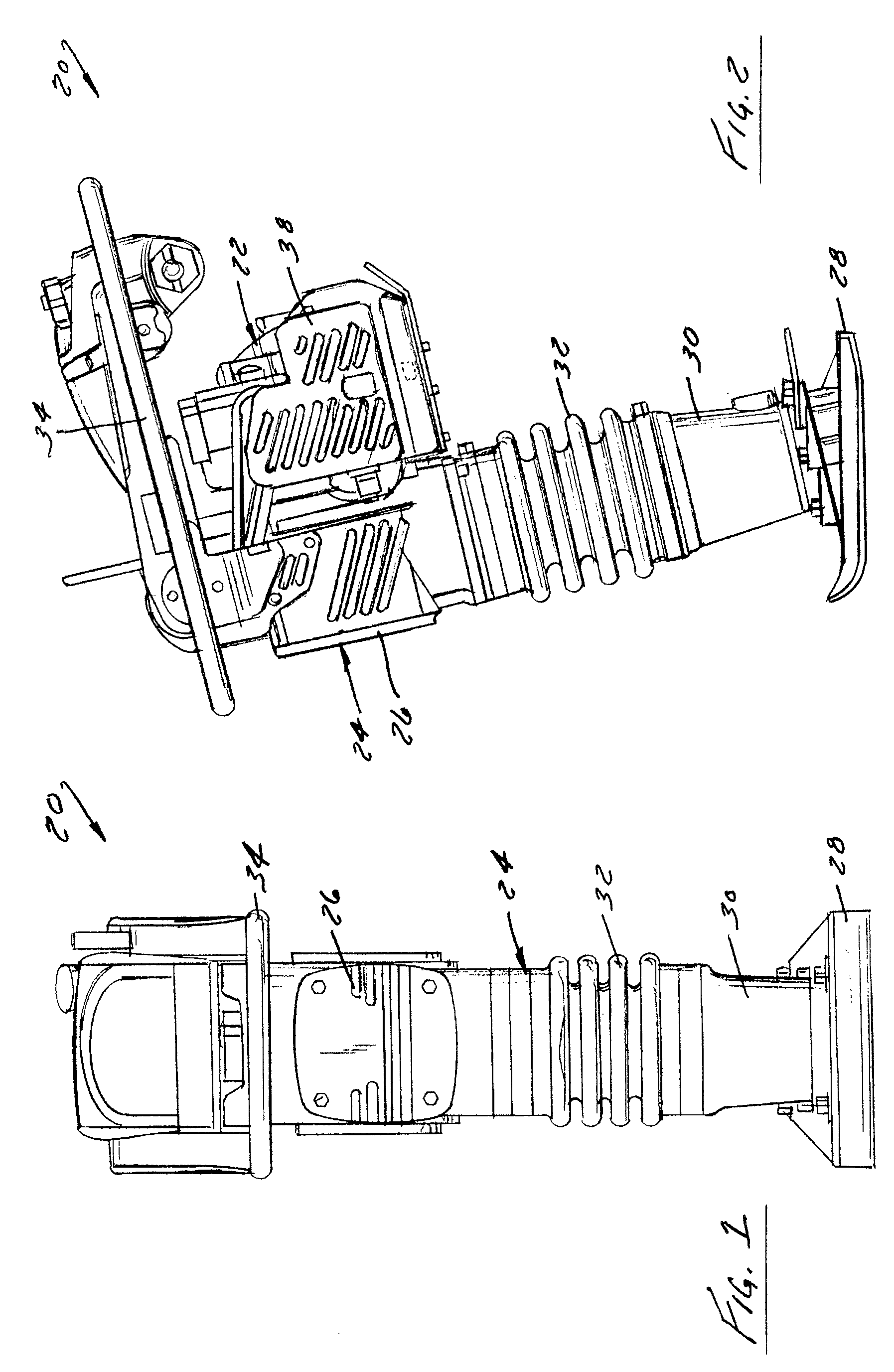
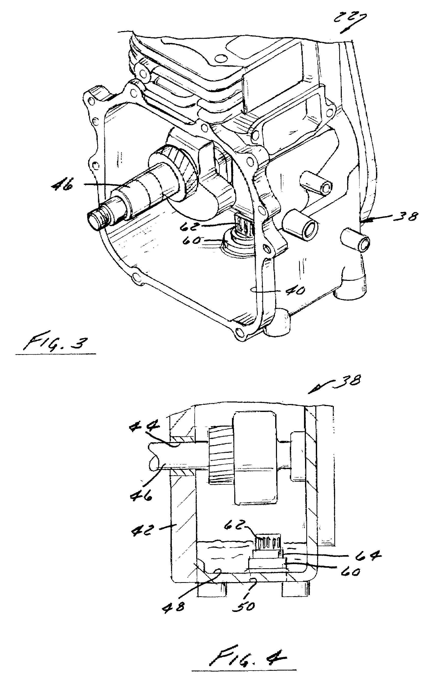
[0031]Referring to FIGS. 5-9, a parallel plate capacitor-type fluid level sensor 62 constructed in accordance with the invention is supported in the housing 64. The sensor 62 includes an integrated circuit board 70, a probe 72, several leads 74, and a remote gauge 76. The gauge 76 is mounted on the rear of the rammer 20 in the vicinity of the rammer's other indicators and controls. Referring to FIG. 7, gauge 76 preferably includes an LED 78 or other indicator that provides a visual indication of a low oil condition, such as a flashing red light. It may also have an internal controller 80, such as an LED integrated circuit board, that coordinates operation of the motor's ignition system and the sensor 62. An additional lead 82 extends from the gauge 76 to the rammer's ignition system. That lead supplies power to the sensor 62 and gauge 76 and may also control the ignition system.

[0032]The integrated circuit board 70 of the sensor 62 contains the necessary electronics for receiving si...

second embodiment

[0040]The controller 180 in the gauge 176 is preferably configured to generate a low oil signal only when the sensor's oscillation period is below a frequency that is indicative of the absence of any oil in the capacitance bridges between the plates 190. Hence, in the second embodiment, the low oil warning signal is generated only when the level in the oil pan 40 is below the bottom of the plates 190. The sensor 162 in effect therefore senses the presence or absence of oil between the plates 190 as opposed to a level of oil between the plates 190. This approach significantly increases the reliability of the sensor 162 and facilitates its design when compared to an approach that attempts to determine the level of oil between the plates 190 because it does not require any sophisticated calibration of the sensor 162 to account for changes in oil properties or temperature.

[0041]In the illustrated example of a rammer, or in any other environment in which vibrations or other factors may l...


PUM


Abstract

A fluid level sensor comprises a parallel plate capacitor coupled to an integrated circuit located in the bottom of an oil pan or other receptacle in which fluid level is being sensed. The sensor is preferably mounted on a drain plug for the receptacle. It includes an integrated circuit board encapsulated in a potting material disposed within the drain plug and a probe extending upwardly from the integrated circuit with its lower end also encapsulated with a resin such that its leads are protected by the resin encapsulating the integrated circuit. The probe may include one or more slotted plates in which capacitance bridges are formed within the slots or a plurality of parallel plates in which capacitance bridges are formed between adjacent plates. The sensor can be used to control operation of a gauge and / or an ignition control circuit for the machine's engine.

Description

CROSS-REFERENCE TO RELATED APPLICATION(S)[0001]This application claims priority from U.S. Provisional Patent Application Ser. No. 60 / 743,134 filed on Jan. 17, 2006, the entire contents of each of which is hereby expressly incorporated by reference into the present application.STATEMENT REGARDING FEDERALLY SPONSORED RESEARCH OR DEVELOPMENT[0002]Not applicable.REFERENCE TO SEQUENCE LISTING, A TABLE, OR A COMPUTER PROGRAM LISTING COMPACT DISC APPENDIX[0003]Not applicable.BACKGROUND OF THE INVENTION[0004]1. Field of the Invention[0005]The invention relates to fluid level sensors and, more particularly, relates to a sensor for sensing the level of oil or another fluid in a receptacle based on changes of capacitance between parallel plates of a parallel plate capacitor. The sensor is particularly well-suited for use in machines that are subject to severe vibrations or otherwise are not amenable to float-type fluid level sensors.[0006]2. Discussion of the Related Art[0007]Fluid level senso...

Claims


Application Information

Patent Timeline
Patent Type & Authority Patents(United States)
IPC IPC(8): F01M11/10B60Q1/00G01F23/00
CPCG01F23/263G01F23/268
Inventor KETELHOHN, CHARLIEZIMPRICH, ROBERTGRIESEMER, PAT
Owner WACKER NEUSON PRODN AMERICAS
Why Eureka
Try Eureka