Method and system for precise drilling guidance of twin wells

a drilling guidance and twin well technology, applied in the direction of directional drilling, borehole/well accessories, survey, etc., can solve the problems of affecting the alignment of the second well with respect to the first well is difficult, and the drilling path of the second well to drift outside, so as to achieve the effect of enhancing oil production

Inactive Publication Date: 2009-01-13
PRIME DOWNHOLE MANUFACTRUING LLC
View PDF24 Cites 17 Cited by
  • Summary
  • Abstract
  • Description
  • Claims
  • Application Information

AI Technical Summary

Benefits of technology

[0007]The system may be used to guide a second horizontal well being drilled near a first horizontal well to enhance oil production from subterranean reservoirs of heavy oil or tar sands. The two parallel wells are to be positioned one above the other and separated by a certain distance, e.g., within the range of 4 to 10 meters, through a horizontal section of a heavy oil or tar deposit. In one embodiment, the method guides a drilling path so that the second horizontal well is a consistent and short distance from the first well by: (1) causing a known electrical current to flow in the metallic casing or liner (collectively “casing”) of the first well to produce a continuous magnetic field in the region about the first well, and (2) using magnetic field sensing instruments in the second well while drilling to measure and calculate accurate distance and direction information relative to the first well so that the driller can correct the trajectory of the second well and position the second well in the desired relationship to the first well.

Problems solved by technology

Aligning a second well with respect to a first well is difficult.
A difficulty with surveying is that a cumulative error arises in the surveyed well path because small errors made at each successive survey point along the well path are introduced into the survey calculation made at subsequent survey points.
The cumulative effect of these small errors may eventually cause the drilling path of the second well to drift outside the specified desired ranges of distance or direction relative to the first well.
The magnetic fields from such a source are subject to magnetic attenuation and distortion by the first well casing, and may also generate a relatively weak magnetic field that is difficult to sense from the desired second well drilling path.

Method used


Image

  • Method and system for precise drilling guidance of twin wells
  • Method and system for precise drilling guidance of twin wells
  • Method and system for precise drilling guidance of twin wells

Examples


Embodiment Construction

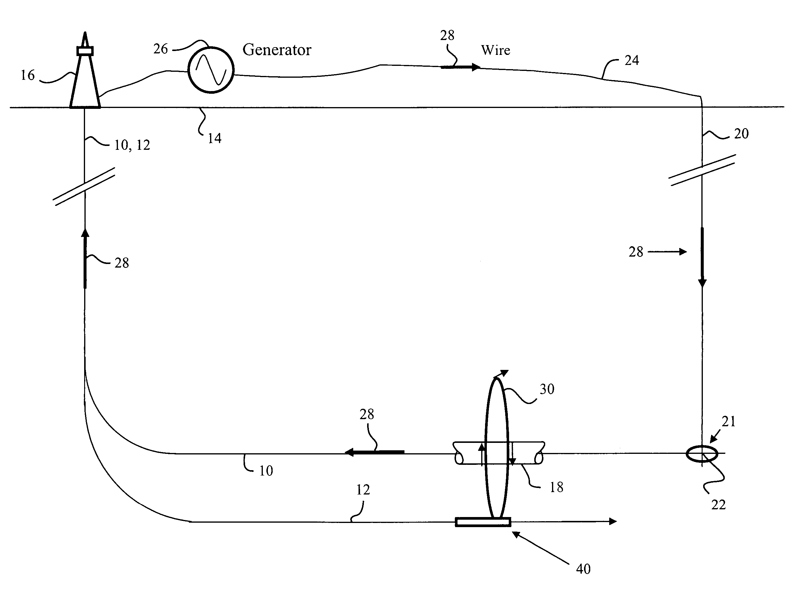
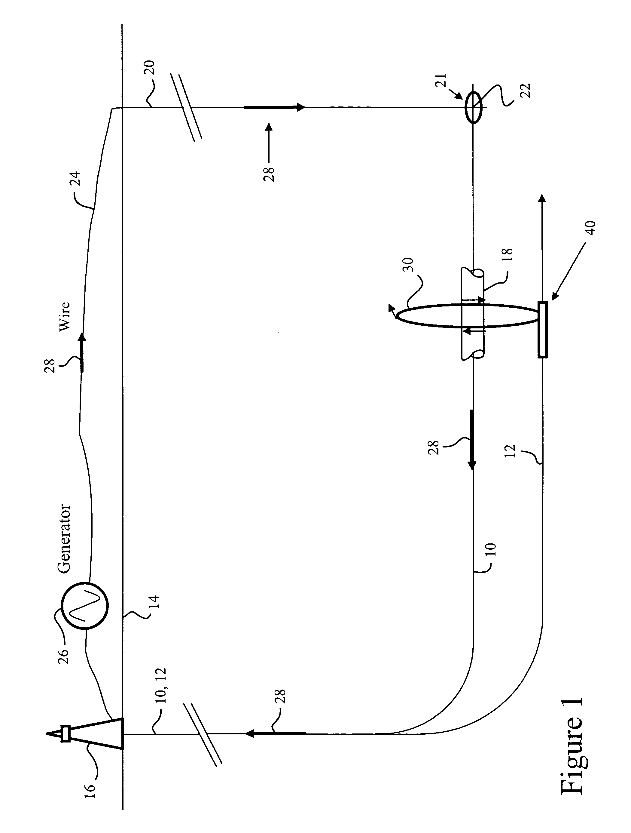
[0015]FIG. 1 schematically illustrates a typical well plan for drilling twin horizontal wells 10, 12. On the ground 14 the wells may be drilled from one or two drilling platforms 16, more likely two. After initially being drilled substantially vertically, the wells are drilled horizontally into a deposit of, for example, heavy oil or tar. The first well 12 is drilled and cased before drilling commences on the second horizontal well 10. The casing or slotted liner are metallic and will conduct electricity. The horizontal portion of the first well may be above the second well by several meters, e.g., 4 to 10 meters.

[0016]A directional survey is made of the first well to map the well and facilitate planning a surface location for a small, vertical borehole 20 which is a third well. This small borehole will nearly intersect 21 the first well at the distal termination end of the first well. The small hole, with a temporary casing installed, preferably of a non-conductive material such as...


PUM


Abstract

A method to guide a drilling path of a second well in proximity to a first well including: applying a time-varying electrical current to a conductive casing or liner of the first well. From the drilling path of the second well, an electromagnetic field generated by the current in the first well is sensed. The drilling path trajectory of the second well is guided using the sensed electromagnetic field.

Description

BACKGROUND OF THE INVENTION[0001]The present invention relates to the field of well drilling guidance and, in particular, to guidance systems that use electromagnetic fields associated with an existing well casing to steer the drilling of a second well proximate to the first.[0002]There is often a need to drill a second well adjacent an existing well. For example, a pair of horizontal wells may be drilled to extract oil from a deposit of heavy oil or tar. Of the pair of wells, an upper well may inject steam into a subterranean deposit of heavy oil or tar while the lower well collects liquefied oil from the deposit. The pair of wells are to be positioned within a few meters of each other along the length of the lateral such that the oil liquefied by the steam from the first well is collected by the second well.[0003]There is a long-felt need for methods to drill multiple wells, e.g., a pair of wells, in juxtaposition. Aligning a second well with respect to a first well is difficult. ...

Claims


Application Information

Patent Timeline
Patent Type & Authority Patents(United States)
IPC IPC(8): E21B7/04E21B47/0228G01V1/42
CPCE21B7/04E21B47/02216E21B47/0228
Inventor WATERS, ROBERT LYNGLE
Owner PRIME DOWNHOLE MANUFACTRUING LLC
Why Eureka
Try Eureka