Monitoring of reservoir fluid moving along flow pathways in a producing oil field using passive seismic emissions

a technology of seismic emission and reservoir fluid, which is applied in seismology for waterlogging, borehole/well accessories, instruments, etc., can solve the problems of elastic rock failure of reservoir rock matrix, increase in shear stress in reservoir rocks, and inability to observe the flow path of reservoir fluid, etc., to achieve optimum reservoir management, improve oil production, and reduce the effect of gas-to-oil ratio

Active Publication Date: 2013-10-24
SAUDI ARABIAN OIL CO
View PDF4 Cites 13 Cited by
  • Summary
  • Abstract
  • Description
  • Claims
  • Application Information

AI Technical Summary

Benefits of technology

[0028]The present invention relates to an improved method of, and system for reservoir monitoring, including identification of the fluid phase (oil or water) moving along flow pathways of hydrocarbon drainage and water movement in a reservoir. These flow pathways are generally along fracture swarms or other zones of weakness in reservoir rock. Microseismic events are detected along these zones of mechanical weakness as the fluids move in the reservoir rocks. Fluids are injected into, or extracted from, a producing reservoir with anomalous flow anisotropy. Water or brine is injected in the pore volumetric space of reservoir rocks to enhance oil production from the reservoir.
[0029]The method of this invention is useful for flood-front mapping in a black oil reservoir system consisting predominantly of oil and water (brine). It is assumed that no free gas is present in the system. Reservoirs containing oil and water, with a low gas-to-oil ratio (GOR), are abundant in giant carbonate fields. These carbonate rocks are extremely heterogeneous and many drilled wells have encountered anomalous fluid flow conduits, or pathways, along narrow fracture swarms. These features contribute to a flow anisotropy that cannot be determined from borehole data alone. Usually, the well spacing in such giant oil fields is sparse. Flood-front monitoring away from and between wells is imperative for optimum reservoir management and for increasing overall recovery. In a producing reservoir, mapping hydrocarbon fluid pathways and identifying respective liquid phase (oil or water) moving along such flow pathways, is crucial for improving and increasing oil recovery.

Problems solved by technology

During the production life of a hydrocarbon reservoir, changes in fluid pressures result in perturbation of the in-situ stresses.
Microseisms result from elastic rock failure of the reservoir rock matrix.
Water injection generates increased reservoir pore pressure which causes an increase in shear stress in reservoir rocks.
This impacts the stability along the planes of weakness present in reservoir rocks, such as joints, bedding planes, faults and fractures.
Similarly, reservoir oil production operations or fluid withdrawal create a pore pressure sink which also affects the stability along the zones of weakness.
Increasing fluid pressure during injection causes a decrease of the effective normal stress and leads to sliding along preexisting sub-critical cracks and fractures.
As the in situ stresses are perturbed by reservoir production and injection activities, the resulting changes in fluid pressure create elastic failure in the rocks and cause microseismic events.
While the above described references disclose various methods and systems for deterring the location of one or more hypocenters, none disclose the delineation of the type of fluid passing through cracks and / or fractions.
However, these models do not detect passive microseismic emissions based upon movement of fluids.
However, this disclosure relates to monitoring of hydraulic fracturing or reservoir stimulation using passive microseismic recordings, and does not in any way attempt to discern the type of liquid moving along a certain pathway in a reservoir.
None of the above references discloses the detection and monitoring of passive microseismic emissions to ascertain the type of fluid moving along a particular region of an oil reservoir.

Method used


Image

  • Monitoring of reservoir fluid moving along flow pathways in a producing oil field using passive seismic emissions
  • Monitoring of reservoir fluid moving along flow pathways in a producing oil field using passive seismic emissions
  • Monitoring of reservoir fluid moving along flow pathways in a producing oil field using passive seismic emissions

Examples


Embodiment Construction

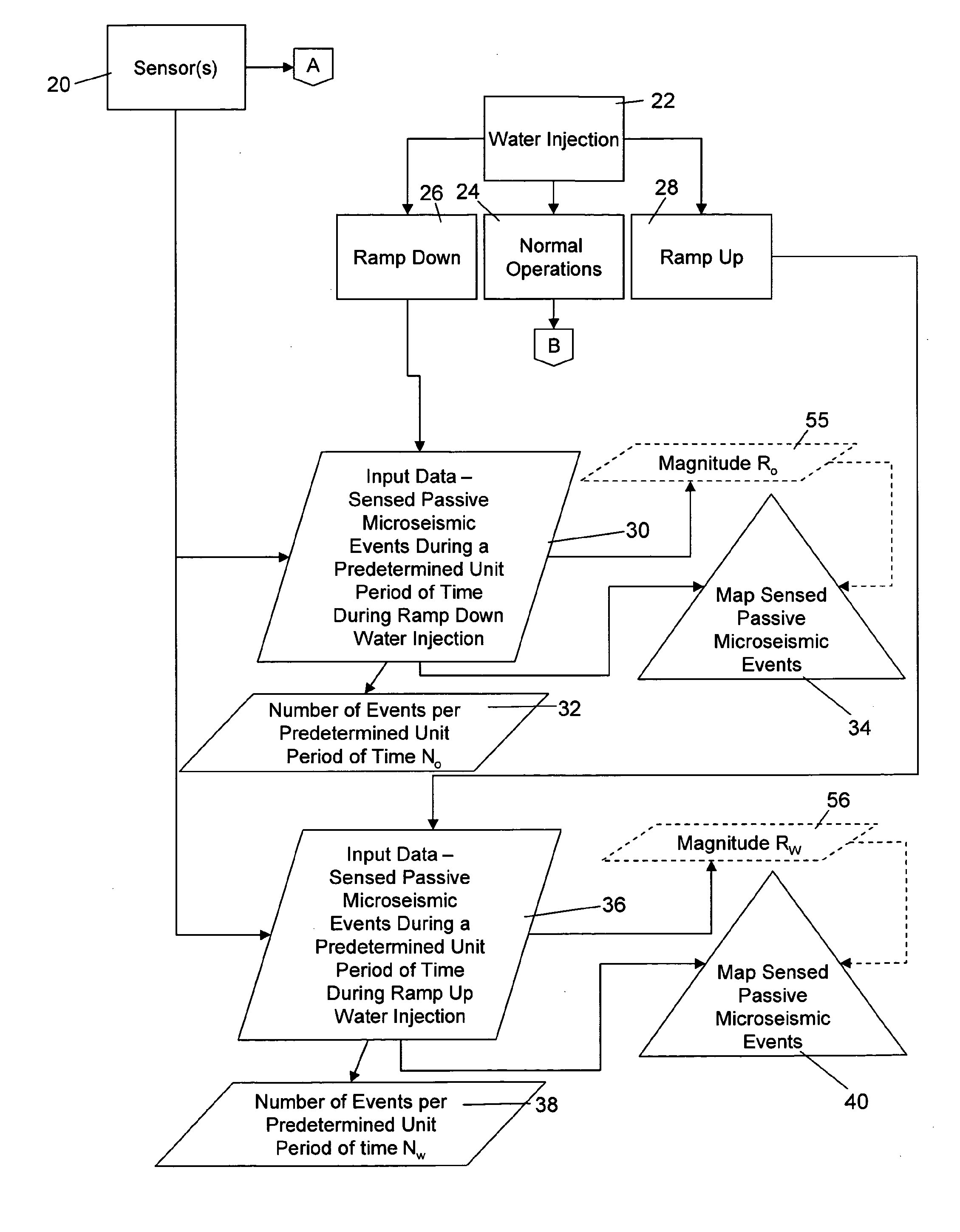
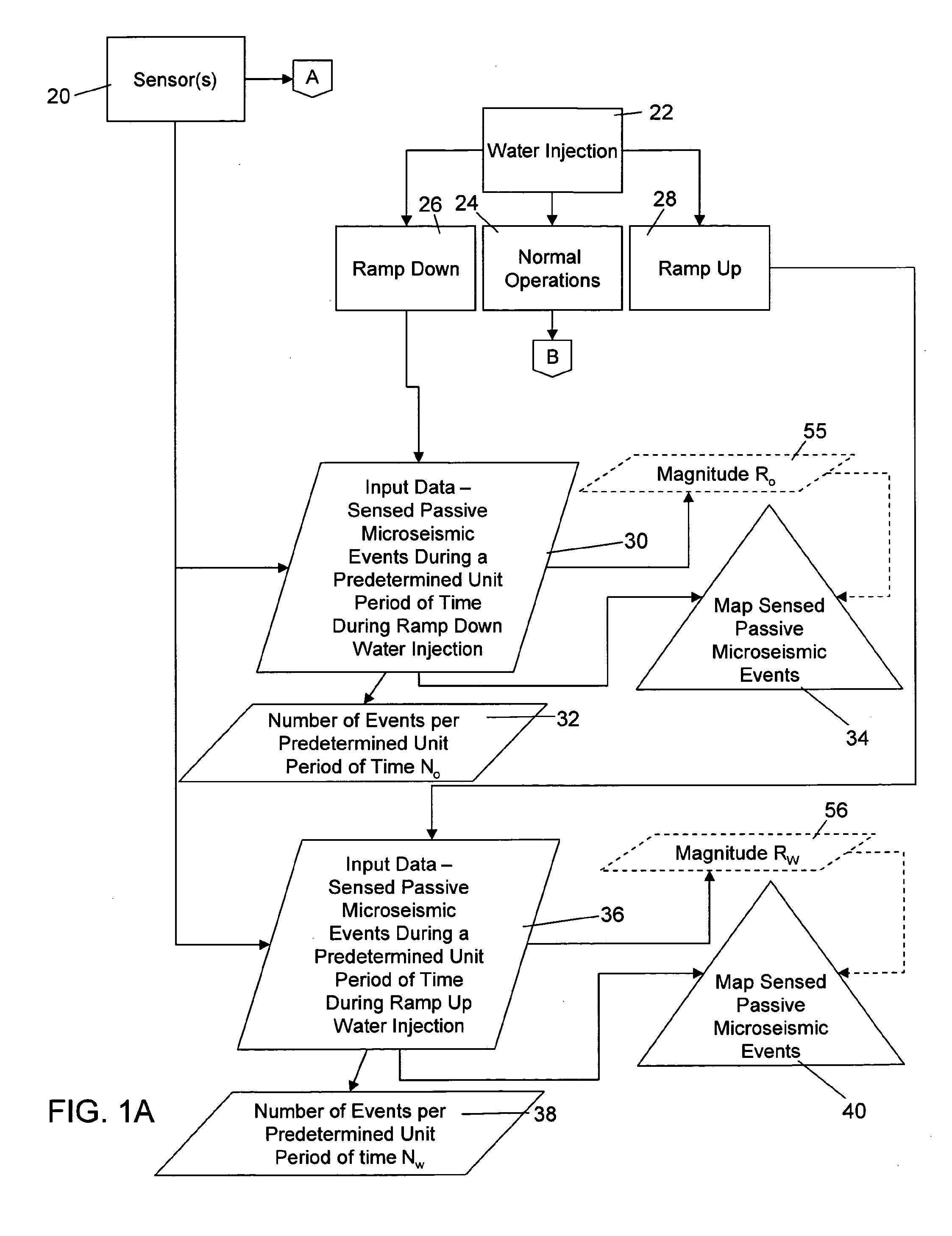
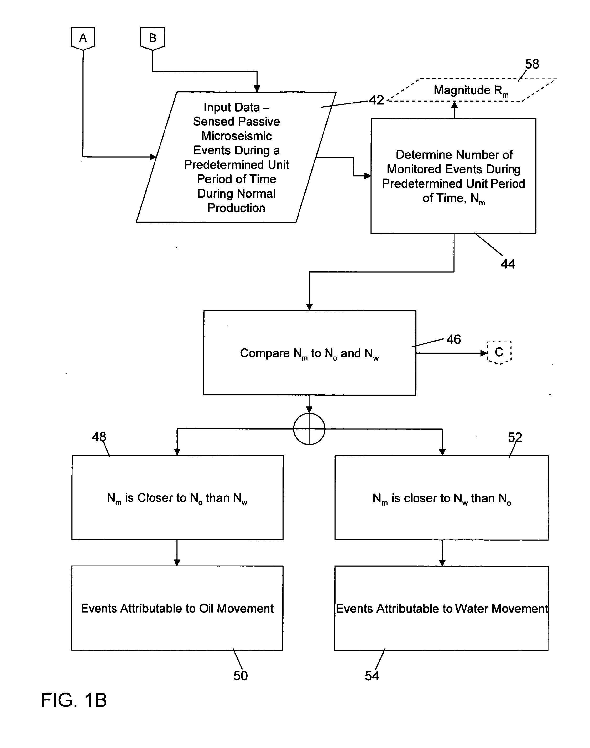
[0043]This invention is particularly useful in a producing reservoir to continuously define the map of preferential fluid movement directions (pathways) and also to identify the type of fluid moving along these preferential pathways. The flow pathways and the fluid phase moving along these pathways between wells cannot be measured easily using conventional measurements in drilled wells. The method and system of the present invention provides the orientation and distribution of preferential fluid pathways and identifies the fluid phase, differentiating between oil or water moving along the pathways. The mapping of fluid pathways and the identification of the type of fluid is useful to optimize fluid injection and production operations and improving overall oil recovery. During monitoring, the detected passive seismic emissions, in certain embodiments recorded and analyzed in real time, can define fluid flow pathways between the wells in a producing field. The water flood-front moveme...


PUM


Abstract

A system of and method for determining whether a liquid moving in an oil-bearing reservoir rock formation is water or oil is provided. The oil-bearing rock formation includes at production well(s) and source(s) of injected water during normal oil production. A fluid pathway is identified, baseline number of passive microseismic events is established, passive microseismic events in the fluid pathway are monitored during oil production to sense microseismic events, the sensed microseismic events are compared to a baseline number of passive microseismic events. The fluid causing the microseismic events is determined to be water if the sensed number of microseismic events approaches the baseline number of passive microseismic events per the predetermined unit, and if the baseline number of passive microseismic is measured during a time period when the water injection is greater than the rate of water injection during normal oil production.

Description

RELATED APPLICATIONS[0001]This application claims the benefit of U.S. Provisional Patent Application No. 61 / 032,794 filed Feb. 29, 2008, the disclosure of which is hereby incorporated by reference.BACKGROUND OF THE INVENTION[0002]1. Field of the Invention[0003]The present invention relates to a method of monitoring reservoir rock containing hydrocarbons, and in particular to a method and system for the identification of the type of liquid moving along flow pathways of a producing field using passive seismic emissions.[0004]2. Description of Related Art[0005]Microseisms in reservoir rock matrixes in producing oil fields are generally the result of pore pressure perturbation and geomechanical stress field relaxation due to liquid movement as reservoir fluids are produced and / or injected. The microseisms, or micro-earthquakes, are generated because the stress field in the reservoir, and fluid flow, is anisotropic. The anisotropy is generally due to heterogeneity in reservoir rocks. Exi...

Claims


Application Information

Patent Timeline
Patent Type & Authority Applications(United States)
IPC IPC(8): E21B49/00
CPCE21B49/008G01V1/30G01V2210/123
Inventor DASGUPTA, SHIVAJI N.
Owner SAUDI ARABIAN OIL CO
Why Eureka
Try Eureka