Nozzle clamping nut for injection valves and method for producing said nozzle clamping nut

a technology of injection valve and clamping nut, which is applied in the direction of hose connection, fuel injecting pump, machine/engine, etc., can solve the conflict between the goal of achieving the required low stress concentration and the need for a clamping nut to be clamped, and achieve the effect of reducing stress concentration, simple manufacturing and increasing the bearing surface of the nozzle body

Inactive Publication Date: 2009-01-13
CONTINENTAL AUTOMOTIVE GMBH
View PDF40 Cites 5 Cited by
  • Summary
  • Abstract
  • Description
  • Claims
  • Application Information

AI Technical Summary

Benefits of technology

[0005]The object of the present invention is to provide a nozzle clamping nut, which achieves a large bearing surface with a low level of stress concentration.
[0009]The two-part configuration of the nozzle clamping nut with the fixed connection between a precision-steel tube and a connector, in particular produced as a single turned part, for use as a nozzle clamping nut makes it possible to reduce the stress concentration when subject to an axial force and torque as well as to increase the bearing surface of the nozzle body in a manner that is simple to manufacture.
[0010]Also the resulting machining volume is significantly reduced due to the simple structure of the individual components. A high level of dimensional accuracy in relation to form and position tolerances is also ensured due to the use of a precision-steel tube.
[0011]The bearing surface of the inner tube is advantageously configured flat in the contact region with the inner wall of the outer tube. This means that the bearing surface of the nozzle clamping nut can be maximized.
[0012]According to one preferred embodiment an adhesive-bonded or soldered connection is provided, to minimize possible stress concentrations in contrast to a welded connection - due to the material connection thereby formed.

Problems solved by technology

The problem here is that a stress concentration occurs on the annular shoulder in the transition region between the bearing surface and the side wall inside the nozzle clamping nut in the loaded state; this can cause cracks to form in the nozzle clamping nut.
One disadvantage of this large transition radius to reduce the stress concentration is however that the remaining flat bearing surface required to tension the nozzle body of the injection nozzle is reduced.
Therefore with the nozzle clamping nuts produced as turned parts according to the prior art, there is a conflict of goals between achieving the required low level of stress concentration and also achieving the required large bearing surface.
One disadvantage of producing the nozzle clamping nut as a turned part is also that the nut is turned from a full piece.
This method is time-consuming and the machining volume is relatively high.

Method used


Image

  • Nozzle clamping nut for injection valves and method for producing said nozzle clamping nut
  • Nozzle clamping nut for injection valves and method for producing said nozzle clamping nut
  • Nozzle clamping nut for injection valves and method for producing said nozzle clamping nut

Examples


Embodiment Construction

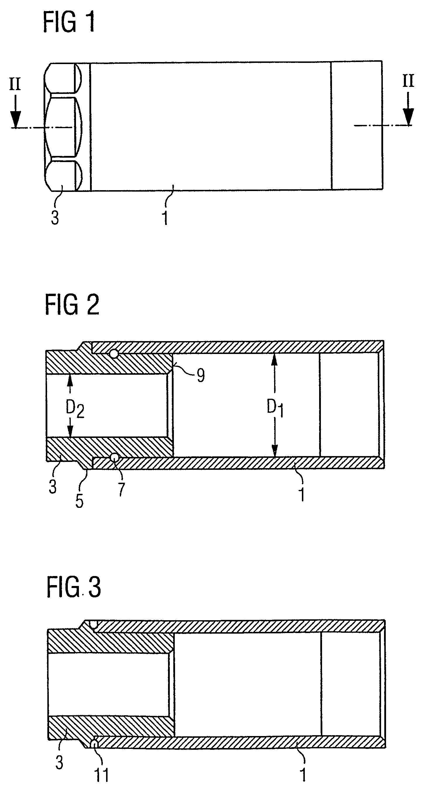
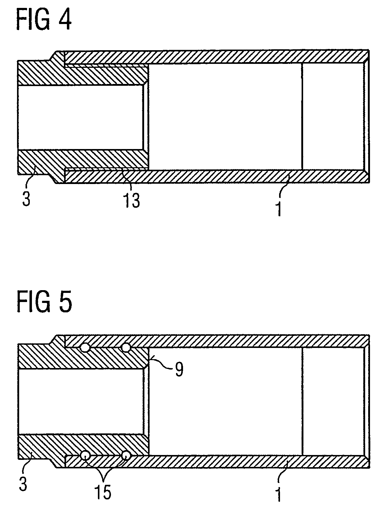
[0017]Four exemplary embodiments of the inventive nozzle clamping nut are described below, shown essentially in longitudinal cross-section diagrams.

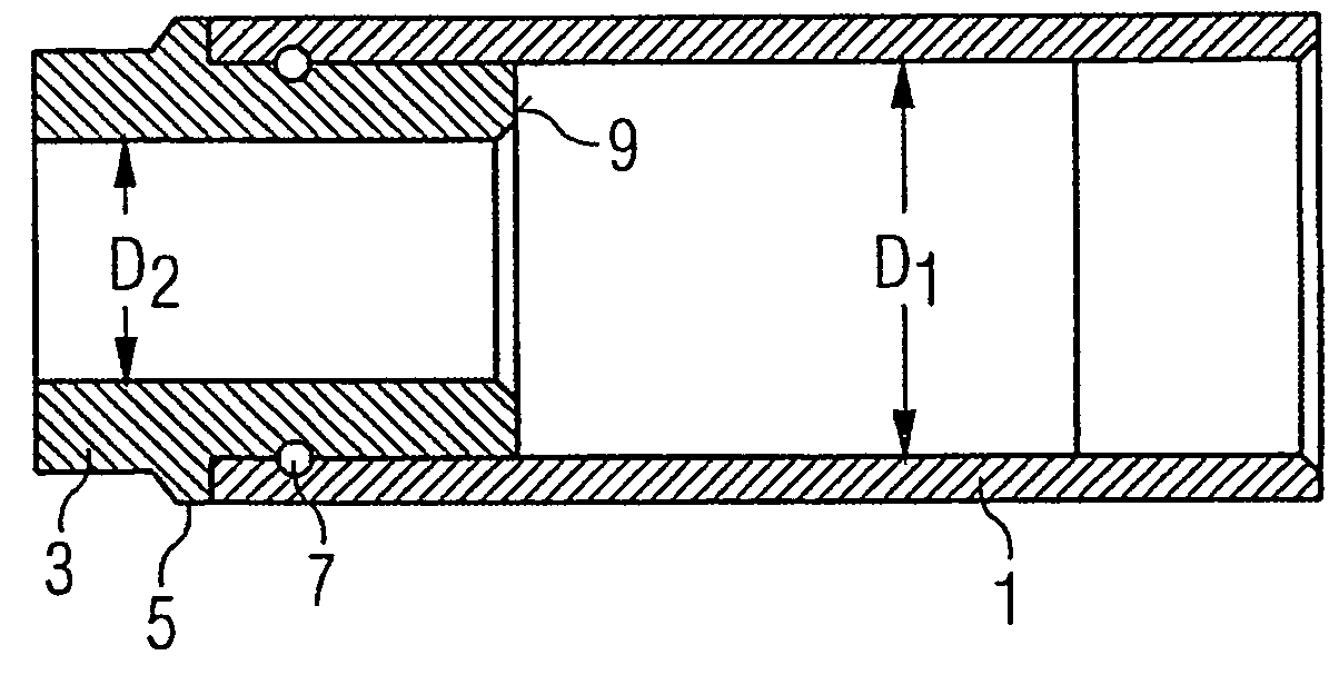
[0018]According to the first exemplary embodiment shown in FIGS. 1 and 2, the nozzle clamping nut comprises a precision-steel tube 1 with a first free inner diameter D1 and a tubular turned part 3 with a smaller second free inner diameter D2. The turned part 3 has a bead 5 projecting in an annular manner on its outer wall, which serves as a stop for the steel tube 1. A circumferential groove 7 for a ring of solder is also provided on the outer wall of the turned part 3. To connect the two tubes 1, 3 in a fixed manner to the nozzle clamping nut, the solder is inserted into the annular groove 7 of the turned part 3 in the form of a ring. The two tubes 1, 3 are then placed on top of each other, the nozzle clamping nut is heated and the solder melts and creeps out of the groove 7 into the intermediate space between the turned part 3 and the ...


PUM


Abstract

A nozzle clamping nut for an injection valve comprises two sections in the longitudinal direction, having different-sized free inner diameters (D1, D2). A shoulder forms a bearing surface (9) in a transition region between the first and second sections, extending in a circular manner perpendicularly to the longitudinal direction. The nozzle clamping nut has a large bearing surface with low stress concentration. The nozzle clamping nut consists of an inner tube (3) and an outer tube (1) which have different-sized inner diameters (D1, D2), which fit inside each other and which are connected to each other in a fixed manner, and the bearing surface (9) is formed by the annular front surface of the inner tube (3).

Description

CROSS REFERENCE TO RELATED APPLICATION[0001]This application is a continuation of copending International Application No. PCT / DE03 / 00057 filed Jan. 9, 2003 which designates the United States, and claims priority to German application no. 102 02 722.6 filed Jan. 24, 2002.TECHNICAL FIELD OF THE INVENTION[0002]The present invention relates to a nozzle clamping nut for an injection valve and a method for producing said nozzle clamping nut.DESCRIPTION OF THE RELATED ART[0003]Such a nozzle clamping nut is known from DE 199 15 685 A1, whereby an injection valve for a common rail injection system of a diesel engine is disclosed. The injection valve comprises a nozzle holder and an injection nozzle fixed to this by means of the nozzle clamping nut. The injection nozzle is held, together with the nozzle holder and the nozzle clamping nut, in a retaining sleeve, with which the injection valve is fixed in the diesel engine. The problem here is that a stress concentration occurs on the annular s...

Claims


Application Information

Patent Timeline
Patent Type & Authority Patents(United States)
IPC IPC(8): B05B17/00F02M61/16
CPCF02M61/16F02M61/168
Inventor HARDT, RAINERLEWENTZ, GUNTERMARKSTEINER, DIETER
Owner CONTINENTAL AUTOMOTIVE GMBH
Why Eureka
Try Eureka