
Arrangement for controlling congestion for multiple host groups sharing a single signaling point code in an IP-based network using respective group congestion levels

a technology of ip-based networks and host groups, applied in data switching networks, frequency-division multiplexes, instruments, etc., can solve problems such as unnecessary traffic cessation for uncongested traffic, and achieve the effect of minimizing the interruption of msu traffi

Active Publication Date: 2009-01-13
CISCO TECH INC
View PDF16 Cites 21 Cited by
  • Summary
  • Abstract
  • Description
  • Claims
  • Application Information

AI Technical Summary

Benefits of technology

The present invention provides an arrangement for a Voice over IP network that allows multiple signaling gateways and call agents to communicate with each other using a single point code while minimizing interruption of traffic from an SS7 node to an IP node within the network. The invention also allows for the deployment of a scalable Voice over IP network that can be easily provisioned based on the use of a prescribed point code and provides a means for controlling congestion for an identified IP node without affecting signaling traffic destined to other IP nodes. The invention uses application server process groups to identify the congestion level for each group and selectively sends a congestion notification message to the originating node based on the priority of the message signaling unit. Overall, the invention improves the efficiency and reliability of Voice over IP networks.

Problems solved by technology

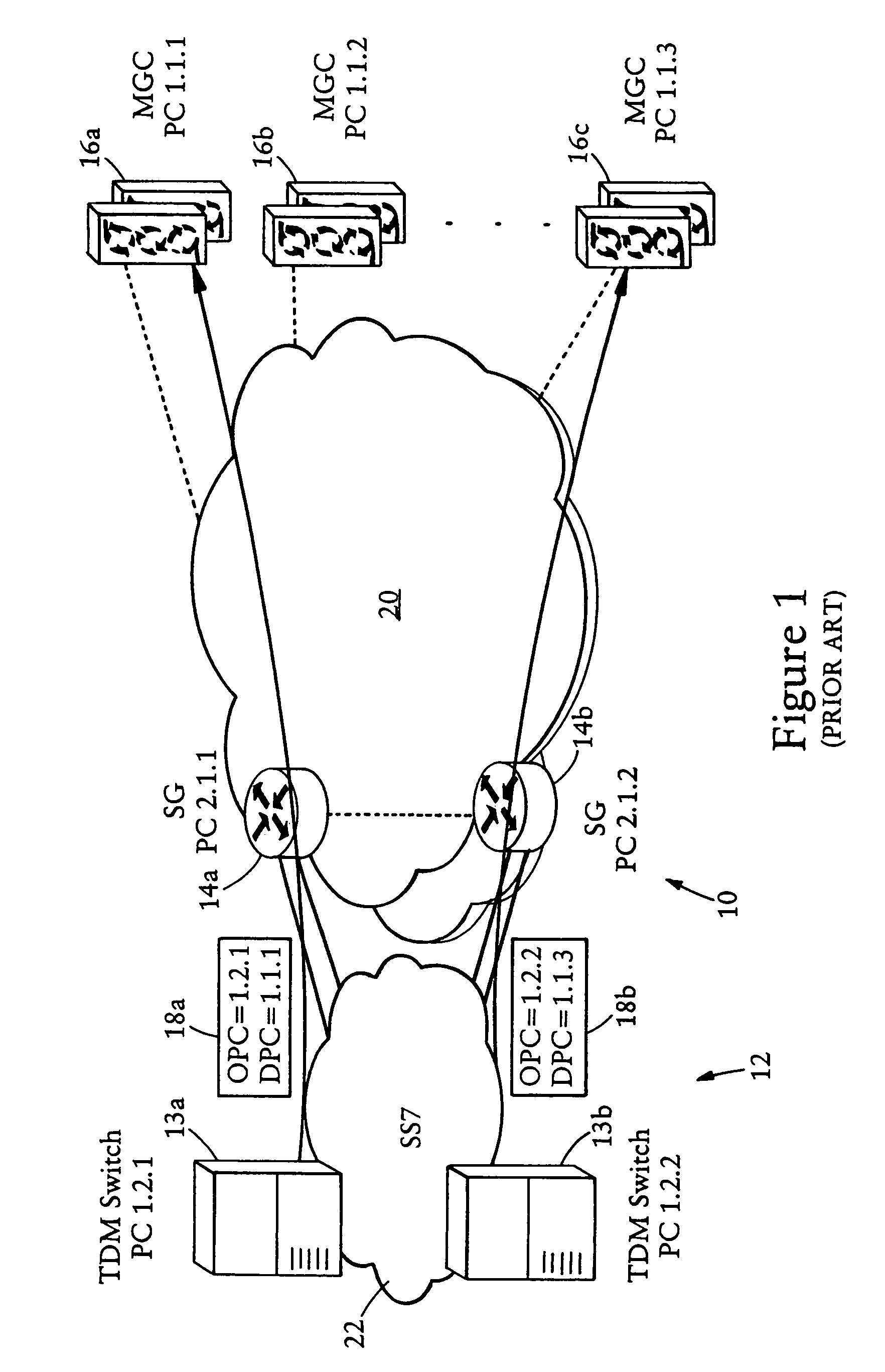
Concerns arise in adding additional Voice over IP-based nodes to accommodate increased traffic and call processing demands within the Voice over IP telephony network.
Sending a TFC based on collective PC congestion level could cause unnecessary traffic cessation for uncongested ASPs or ASPs that are congested at lower levels.

Method used


Image

  • Arrangement for controlling congestion for multiple host groups sharing a single signaling point code in an IP-based network using respective group congestion levels
  • Arrangement for controlling congestion for multiple host groups sharing a single signaling point code in an IP-based network using respective group congestion levels
  • Arrangement for controlling congestion for multiple host groups sharing a single signaling point code in an IP-based network using respective group congestion levels

Examples


Embodiment Construction

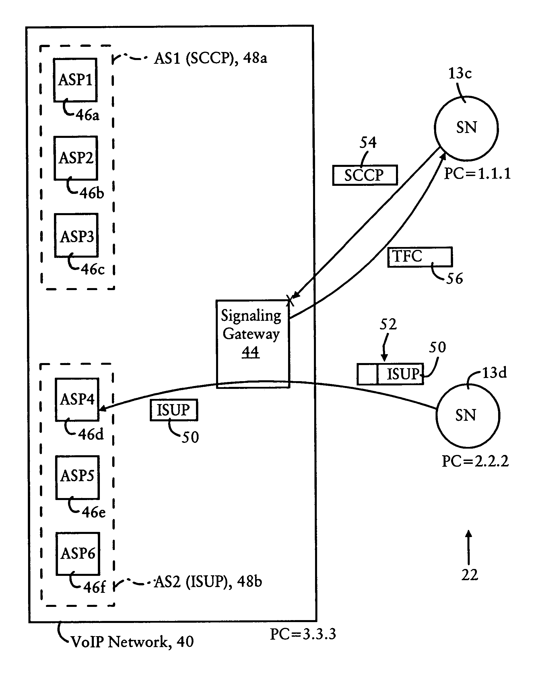
[0032]FIG. 3 is a block diagram illustrating a Voice over IP network 40 configured for interfacing with an SS7 signaling network 22, according to an embodiment of the present invention. As illustrated in FIG. 3, the signaling network 22 includes SSP-capable PSTN switches 13c and 13d having respective point codes 1.1.1, and 2.2.2. Although not shown in FIG. 3, the SS7 signaling network 22 could include a mated pair of switching transfer points (STPs) for routing signaling traffic.

[0033]The Voice over IP network 40 includes signaling message transfer nodes, for example signaling gateways and call agents, sharing the same point code 3.3.3. For simplicity, a single signaling gateway 44 is illustrated, although typically the Voice over IP network 40 will include multiple signaling gateways 44 that communicated with mated STPs. The signaling gateway 44 is also referred to as an IP Transfer Point (ITP).

[0034]The Voice over IP network 40 also includes call agents (i.e., media gateway contro...


PUM


Abstract

AVoice over IP network, having multiple application server processes (ASPs) and at least one signaling gateway, communicates with switched circuit network nodes using a prescribed point code. The ASPs are arranged into ASP groups, each ASP group identifying the ASPs configured for processing prescribed message signaling unit (MSU) types. The signaling gateway determines a congestion level for each ASP group. Upon receiving an SS7 message specifying the prescribed point code as the destination point code and carrying a MSU, the signaling gateway selects one of the ASP groups based on identifying a matching MSU type. If the signaling gateway determines that the priority of the MSU is less than the determined congestion level for the ASP group, the signaling gateway drops the MSU and sends back a Transfer Controlled message to the originating signaling node.

Description

BACKGROUND OF THE INVENTION[0001]1. Field of the Invention[0002]The present invention relates to Voice Over IP telephony; more particularly, the present invention relates to transport of common channel SS7 signaling messages (e.g., Message Transfer Part 3 (MTP3)) by a signaling gateway, received from a circuit switched network node having a prescribed point code, to a call agent according to a prescribed Voice Over IP telephony protocol such as MTP3 User Adaptation Layer (M3UA) or SCCP User Adaptation (UA) Layer (SUA).[0003]2. Description of the Related Art[0004]Common Channel Interoffice Signaling (CCIS) networks provide out of band signaling for telecommunications networks such as public switched telephone networks. Most of the signaling communications for telephone networks utilize Signaling System 7 (SS7) protocol. An exemplary SS7 compliant CCIS network includes Service Switching Points (SSPs) (i.e., an SS7 capable telephony switch), Signaling Transfer Points (STPs), and data l...

Claims


Application Information

Patent Timeline
Patent Type & Authority Patents(United States)
IPC IPC(8): H04L12/28
CPCH04L65/104H04L65/80
Inventor PETERSON, LARRY EARLDETERS, VINCENT L.
Owner CISCO TECH INC
Learn More