Locking system for a cotton candy machine

a locking system and cotton candy technology, applied in the field of cotton candy machines, can solve the problems of inconfigurable locking system b>42/b> and damage to the machine, and achieve the effect of preventing inadvertent operation

Active Publication Date: 2009-01-20
GOLD MEDAL PRODS
View PDF13 Cites 3 Cited by
  • Summary
  • Abstract
  • Description
  • Claims
  • Application Information

AI Technical Summary

Benefits of technology

[0017]Prior to transport of the cotton candy machine, the user locks the machine by rotating the handle upwardly. As the handle is rotated upwardly, the cam members rotate into engagement with the motor mount to lock the machine. In one embodiment, a portion of the handle extends over the spinner head when the machine is locked and thereby prevents a user from mounting the basket to the machine. In this way, the user is prevented from inadvertently operating the machine while it is in the locked position. The handle also provides the user with an ergonomic means for carrying the machine between different locations.

Problems solved by technology

Also, the locking system 42 is not configured to prevent a user from inadvertently transporting the machine 10 in an unlocked position or attempting to operate the machine while it is in the locked position.
Either of these conditions could result in damage to the machine 10.

Method used


Image

  • Locking system for a cotton candy machine
  • Locking system for a cotton candy machine
  • Locking system for a cotton candy machine

Examples


Embodiment Construction

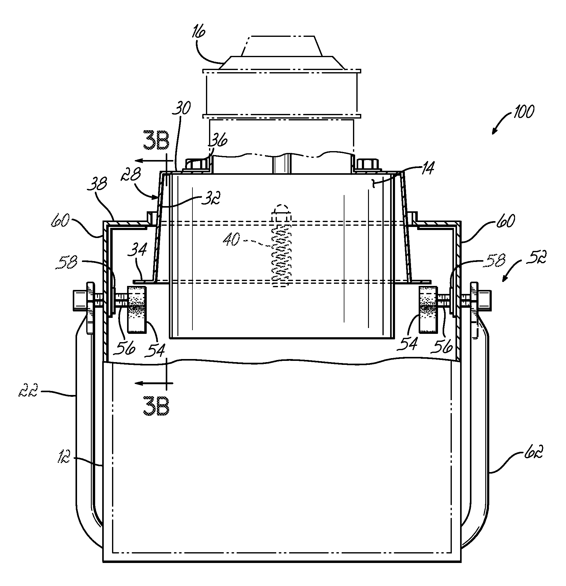
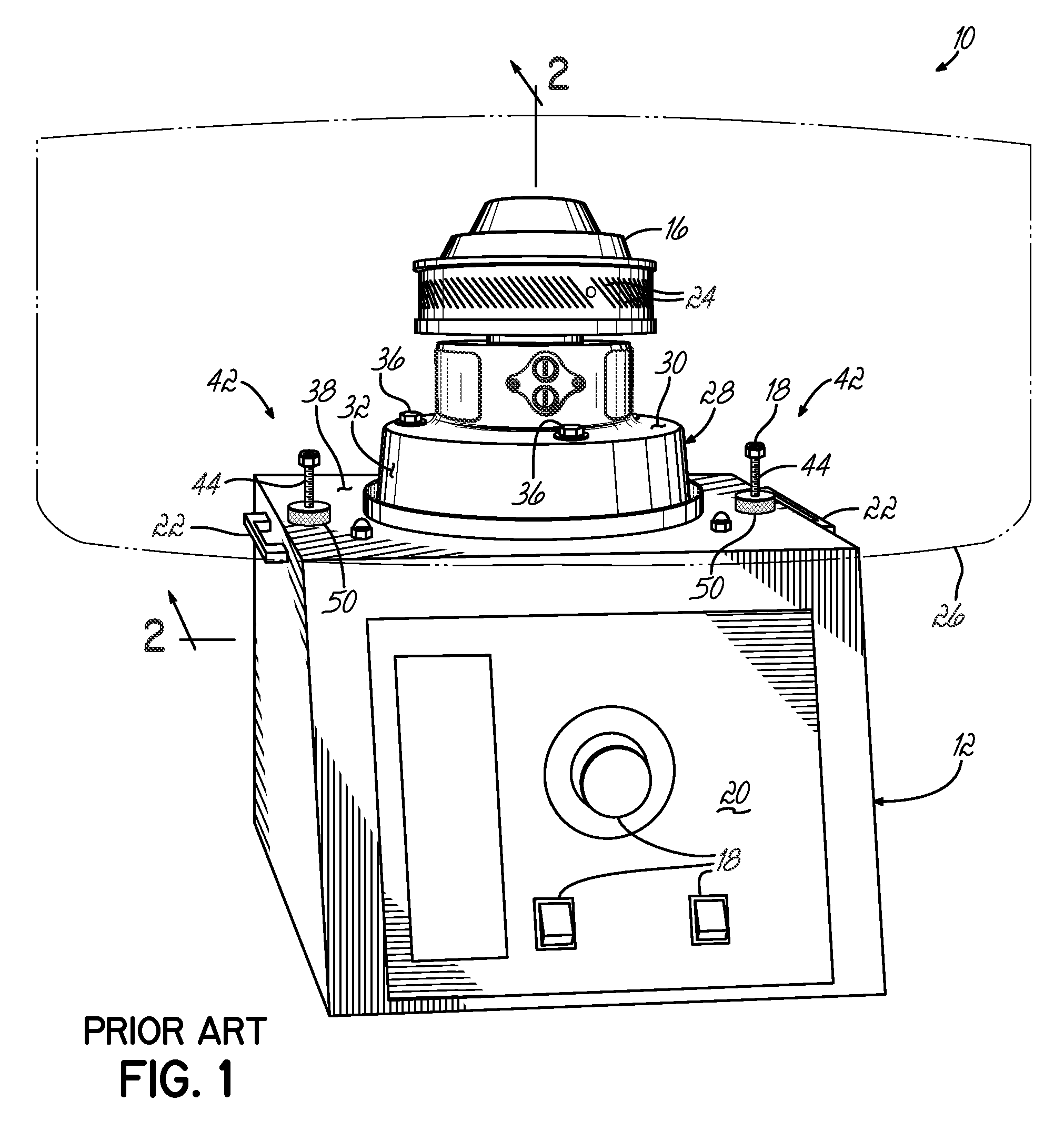
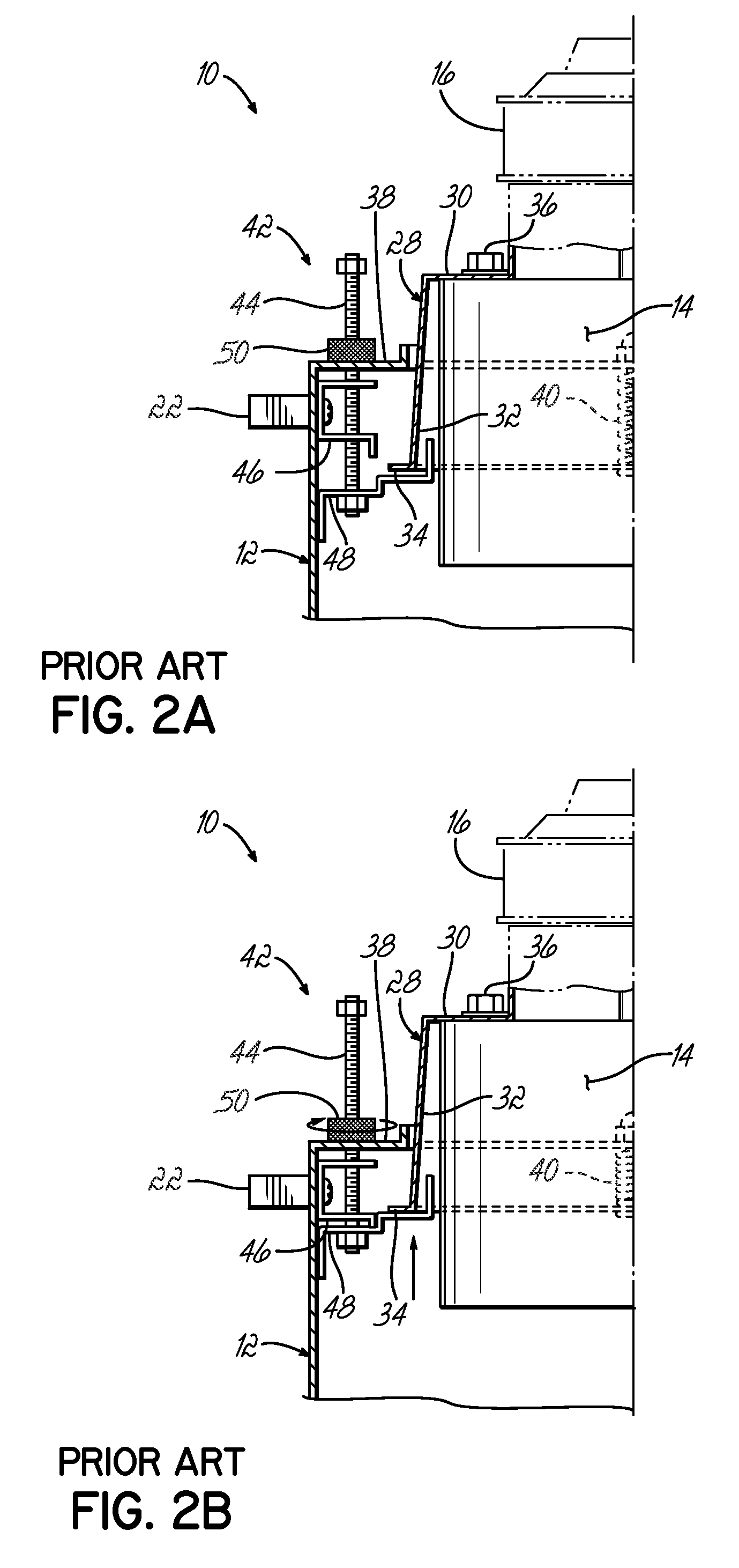
[0032]Referring now to FIGS. 3, 3A, 3B, 4, 4A and 4B, a locking system 52 is shown for locking and unlocking a cotton candy machine 100 in accordance with one embodiment of the present invention, where like numerals represent like parts to the cotton candy machine 10 shown in FIGS. 1, 2A and 2B. The locking system 52 is provided to lock the motor mount 28 in a locked position (FIGS. 4, 4A and 4B) for safe transport of the cotton candy machine 100 and unlock the motor mount 28 prior to use of the machine 100 (FIGS. 3, 3A and 3B). In the unlocked position as shown in FIG. 3A, the motor mount 28 is suspended from the top wall 38 of the base 12 by the springs 40 so that the motor mount 28, and the motor 14 supported thereby, float relative to the base 12. In the locked position as shown in FIGS. 4, 4A and 4B, the motor mount 28 is rigidly supported or locked relative to the base 12.

[0033]In one embodiment, as shown in FIGS. 3A and 3B, the locking system 52 includes a pair of spaced apar...


PUM

PropertyMeasurementUnit
circumferenceaaaaaaaaaa
vibrational forcesaaaaaaaaaa
vibrationalaaaaaaaaaa

Abstract

A locking system for a cotton candy machine includes a pair of rotatable cam members that are selectively engagable and disengagable from a motor mount of the machine to alternatively lock and unlock the machine. A rotatable handle or a pair of rotatable levers are operatively connected to the cam members to selectively rotate the cam members to the locked and unlocked positions.

Description

FIELD OF THE INVENTION[0001]The present invention relates generally to cotton candy machines and, more particularly, to locking systems used in connection with cotton candy machines to lock the machines for safe transport and unlock the machines prior to use.BACKGROUND OF THE INVENTION[0002]Machines for spinning granular sugar into sugar filaments or so-called cotton candy are known and have been employed for some time to produce cotton candy. One known cotton candy machine, designated by numeral 10 in FIGS. 1, 2A and 2B, includes a base 12, a motor 14 housed within the base 12, and a spinner head 16 connected to the motor 14 through a rotatable shaft (not shown). Controls 18 are provided on a front panel 20 of the base 12 for controlling operation of the machine 10 as will be understood by those of ordinary skill in the art. A pair of handles 22 are mounted on opposite sides of the machine 10 so that a user can carry or transport the machine 10 to different locations.[0003]In use, ...

Claims


Application Information

Patent Timeline
Patent Type & Authority Patents(United States)
IPC IPC(8): A23G3/02
CPCA23G3/10
Inventor WEISS, RONALD R.
Owner GOLD MEDAL PRODS
Why Eureka
Try Eureka