Breast pump

a breast pump and breast technology, applied in the field of breast pump, can solve the problems that the breast pump cannot stimulate the particular area intensively, the breast cannot be securely held by the breast pump, and the breast is deformed, so as to achieve the effect of effectively promoting the production of mother's milk

Active Publication Date: 2009-01-20
PIGEON CORP
View PDF6 Cites 7 Cited by
  • Summary
  • Abstract
  • Description
  • Claims
  • Application Information

AI Technical Summary

Benefits of technology

[0077]As illustrated in FIG. 7, a stimulating convex 473 is formed only on one side, a side beneath the breast in this figure, for example, of a deformable member 470 in this modified example. A vent opening 453 is disposed only on a lower side of a horn member 450 in correspondence with the stimulating convex 473. When the breast is brought into contact with the deformable member 470 as illustrated in FIG. 7, producti

Problems solved by technology

Since the large cup 41 is entirely deformed, the conventional breast pump cannot intensively stimulate th

Method used


Image

  • Breast pump
  • Breast pump
  • Breast pump

Examples


embodiment 1

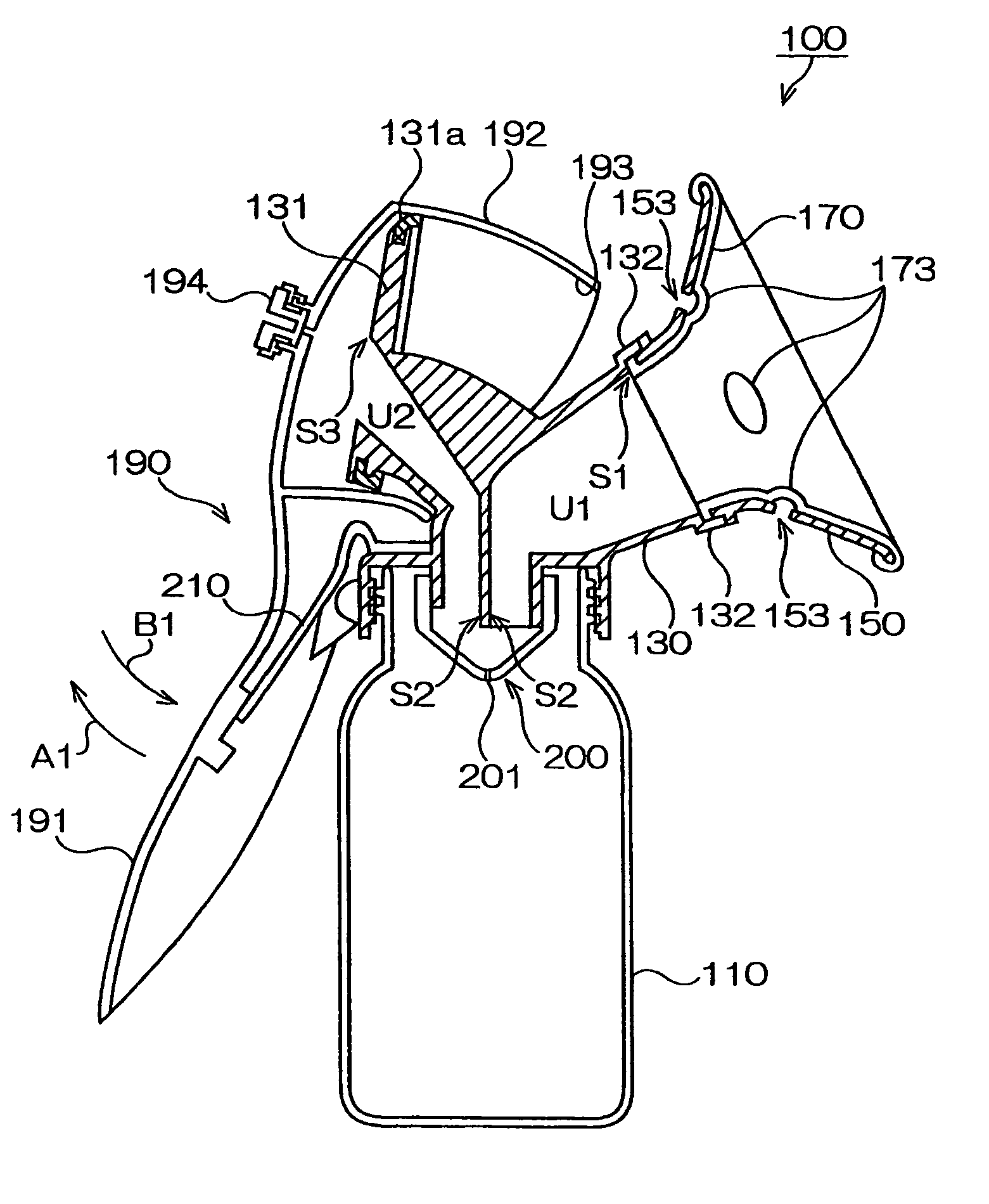
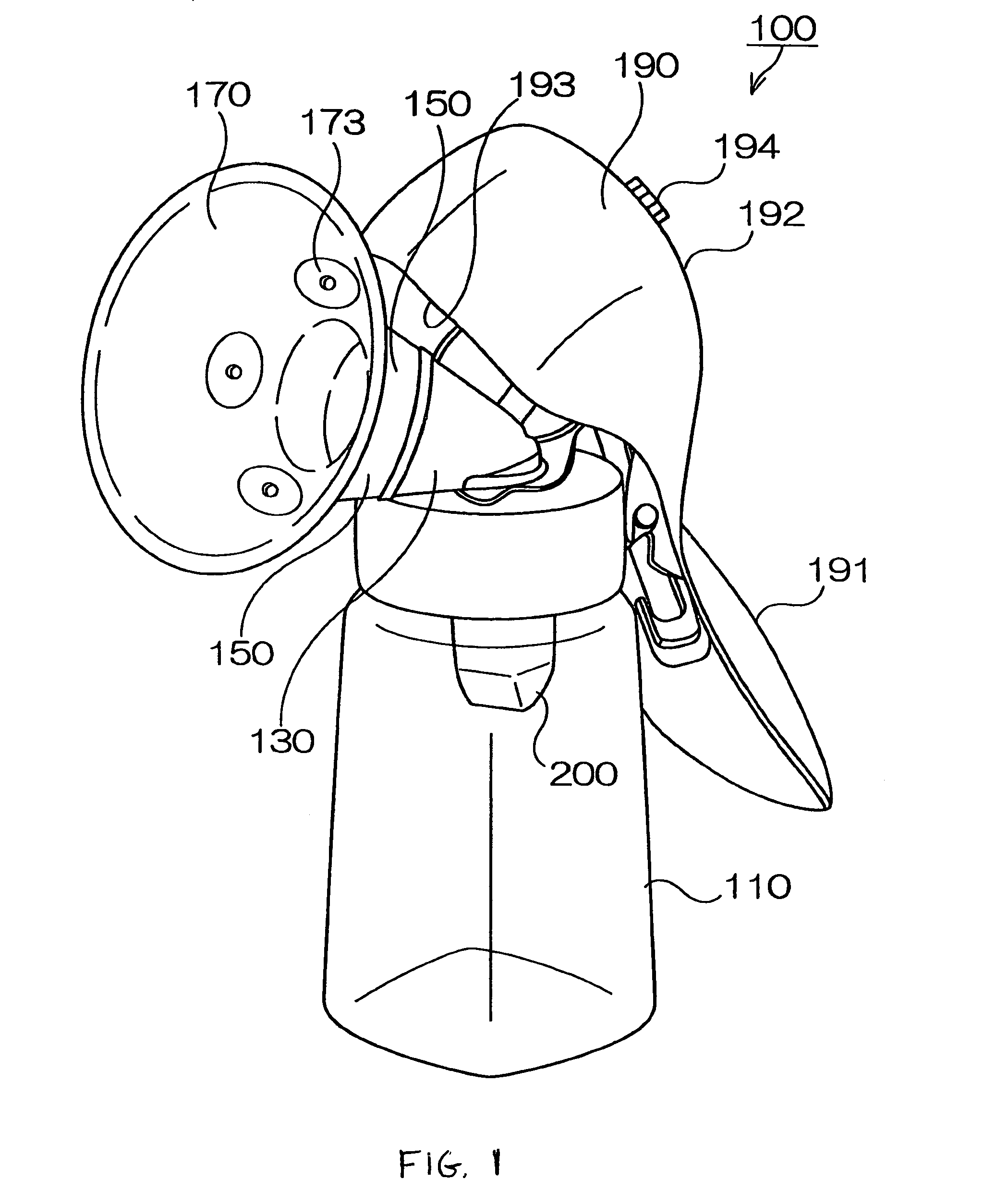
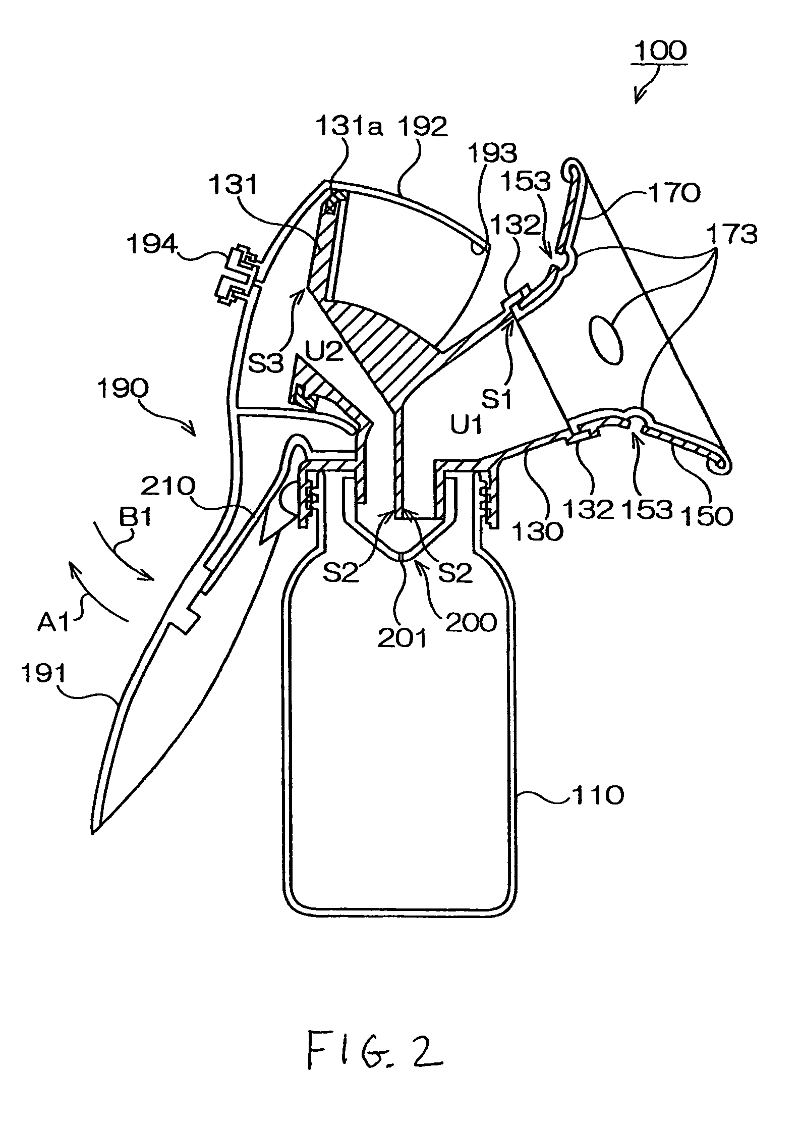
[0037]FIG. 1 is a perspective view schematically illustrating a manual breast pump 100 in a first embodiment according to the present invention, and FIG. 2 is a schematic cross-sectional view of the manual breast pump 100 in FIG. 1.

[0038]As illustrated in FIG. 1, the manual breast pump 100 has a milk container main body for accommodating sucked milk such as a milk bottle 110. The milk bottle 110 is made from glass or plastic resin such as PES (polyethersulfone), polycarbonate and polypropylene.

[0039]A communicating portion 130 is provided in the vicinity of an opening (in the upper region) of the milk bottle 110 in such a position as to cover the opening of the milk bottle 110. The communicating portion 130 has a first opening S1 disposed in the upper right, a second opening S2 in the lower region, and a third opening S3 in the upper left in FIG. 2.

[0040]A first vent passage U1 is formed between the first opening S1 and the second opening S2, and a second vent passage U2 is formed b...

example modified from embodiment 1

[0076]FIG. 7 schematically illustrates a manual breast pump 400 in an example modified from the first embodiment. Since many structures included in the manual breast pump 400 in this example are similar to those of the manual breast pump 100 in the first embodiment, reference numbers and the like similar to those in the first embodiment are given to the similar structures and the description of those is omitted. The modified example is now described while putting emphasis on its different points from the first embodiment.

[0077]As illustrated in FIG. 7, a stimulating convex 473 is formed only on one side, a side beneath the breast in this figure, for example, of a deformable member 470 in this modified example. A vent opening 453 is disposed only on a lower side of a horn member 450 in correspondence with the stimulating convex 473. When the breast is brought into contact with the deformable member 470 as illustrated in FIG. 7, production of mother's milk can be effectively promoted ...

embodiment 2

[0081]FIG. 8 schematically illustrates a main part of a manual breast pump 300 in a second embodiment according to the invention. Since many structures included in the manual breast pump 300 in FIG. 8 are similar to those of the manual breast pump 100 in the first embodiment, reference numbers and the like similar to those in the first embodiment are given to the similar structures and the description of those is omitted. The second embodiment is now described while putting emphasis on its different points from the first embodiment.

[0082]As illustrated in FIG. 8, the second embodiment is different from the first embodiment in that the horn member and the communicating portion are not separated but formed as a communicating portion 330 including the horn member. That is, the communicating portion 130 and the horn member 150 in the first embodiment are formed as the one-piece communicating portion 330 which has a horn area to be attached to the breast.

[0083]The communicating portion 3...


PUM


Abstract

[Problem] To provide a breast pump capable of securely holding a breast of a user and intensively stimulating a particular potion of the breast.
[Means for Resolution] A breast pump 100 including a milk container main body 110; deformable means 170 for forming a sealed space; a horn member 150; space internal pressure altering means 190 for alternately providing a negative pressure condition and an atmospheric pressure condition in the sealed space; and a communicating portion 130, wherein: the horn member has a base end portion 151 disposed near the communicating portion and an opening end 152 disposed near an entrance through which the breast is inserted; the deformable means covers the inner surface of the horn member 150 and has a base end side attachable and detachable portion171 to be fixed to the base end of the horn member and an opening side attachable and detachable portion 172 to be fixed to the opening end of the horn member; the deformable means has a stimulating convex 173 disposed between the base end side attachable and detachable portion and the opening side attachable and detachable portion; and the horn member has atmospheric pressure condition creating means for maintaining an atmospheric pressure condition in a space between the stimulating convex and the horn member.

Description

TECHNICAL FIELD[0001]The present invention relates to an improvement of a breast pump such as a manual breast pump operated manually and an electrically-powered breast pump driven by a motor or other means, providing a breast pump capable of periodically varying suction pressure.BACKGROUND ART[0002]As a manual breast pump or other which includes a suction pump or other component operated by a user, a type having a deformable sucking portion has been proposed (see Patent Reference No. 1, for example). As illustrated in FIG. 1 of Patent Reference No. 1, a manual breast pump includes a large cup 41 made from elastic material to directly contact a breast of the user, and a shell 43 made from rigid material and disposed outside the large cup 41. When a suction pump 5 is operated with the large cup 41 attached to the breast of the user, negative pressure is generated within the large cup 41. Then, the large cup 41 made from elastic material is sucked toward the breast and thus presses the...

Claims


Application Information

Patent Timeline
IPC IPC(8): A61M1/06A61M1/00
CPCA61M1/0013A61M1/066A61M1/61
Inventor TASHIRO, MITSUO
Owner PIGEON CORP
Why Eureka
Try Eureka