
Flat cable

a flat cable and cable technology, applied in the field of flat cables, can solve the problems of poor shielding efficiency of the former, interference problem in the transmission of high frequency signals, and high cost, and achieve the effects of high performance/price ratio, efficient transmission of high frequency signals, and simple structur

Active Publication Date: 2009-01-20
LOTES
View PDF1 Cites 1 Cited by
  • Summary
  • Abstract
  • Description
  • Claims
  • Application Information

AI Technical Summary

Benefits of technology

The present invention provides a flat cable that has a simple structure and can efficiently transmit high frequency signals. It has a high performance / price ratio, making it desirable to manufacture in bulk. The flat cable has multiple layers of conductors arranged in an insulator. The length of the conductors in the middle layer is shorter than or equal to that of the conductors in the two contiguous layers. This design allows for high frequency signal transmission and makes the cable cost-effective and efficient to manufacture.

Problems solved by technology

Thus, comparing with the twisted pair cable, the performance of the coaxial cable and the optical fiber cable is better; that is, high frequency signal can be transmitted, and the transmission speed is fast, but the cost is more expensive.
The shielding efficiency of the former is worse, and there is still an interference problem in transmitting high frequency signals.
The shielding efficiency of the latter is very good, the division property is also fine, but the cost is too expensive to manufacture in bulk.

Method used


Image

  • Flat cable
  • Flat cable
  • Flat cable

Examples


Embodiment Construction

[0014]The following further describe the invention with the attached figures and the embodiments.

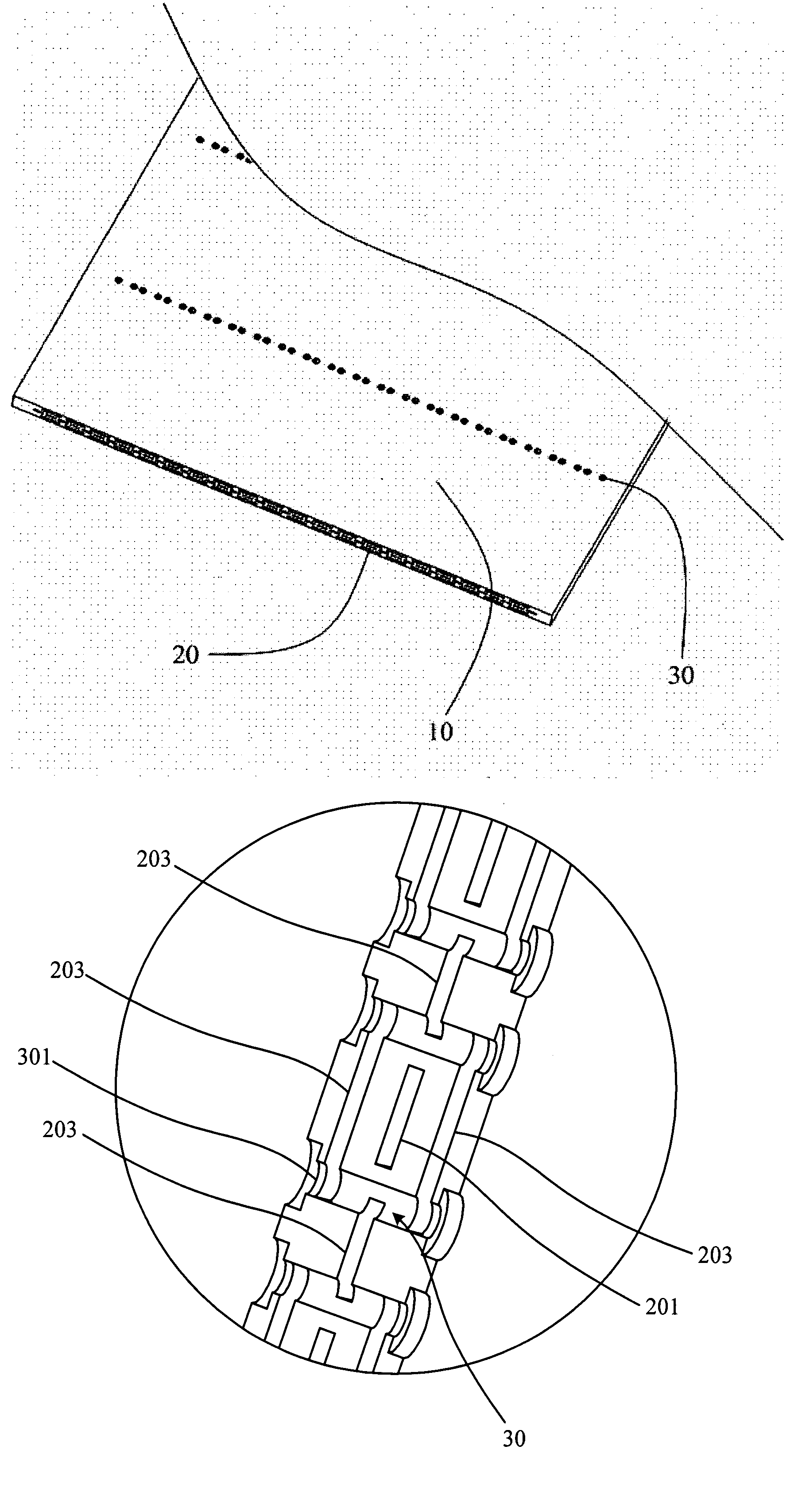
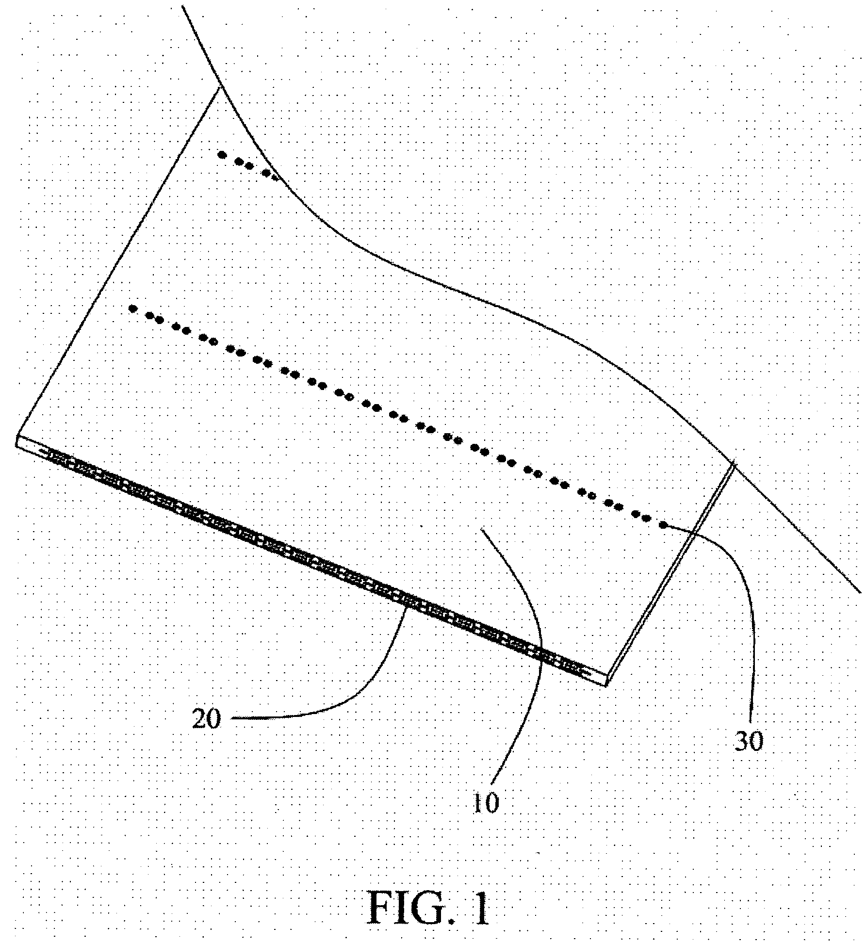
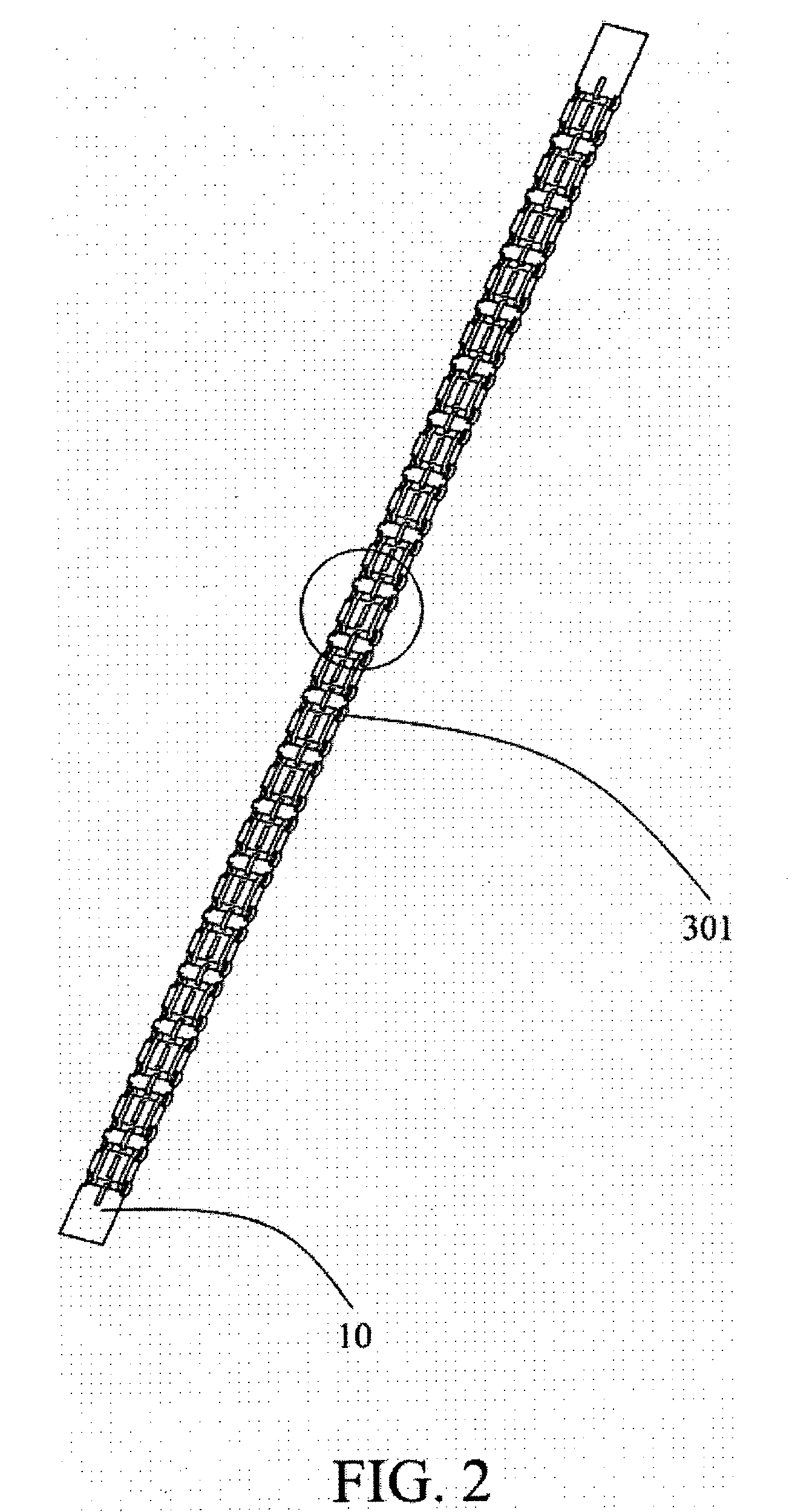
[0015]Referring to FIGS. 1 to 3, a flat cable of the invention includes an insulator 10 and a plurality of conductors 20. The conductors 20 are disposed in several layers in the insulator 10.

[0016]The conductors 20 include a plurality of signal conductors 201 and a plurality of shielding conductors 203. The conductors 20 are arranged in three layers in the insulator 10. The signal conductors 201 are disposed in the middle layer. Those disposed in the upper layer and the lower layer are the shielding conductors 203, whose width is longer than that of the signal conductors 201. Those disposed at the sides of the conductors 201 in the same level as the conductors 201 are another two shielding conductors 203; in other words, the signal conductors 201 are at the center, and there are grounded shielding conductors 203 on the four sides: top, bottom, right, and left, and the shielding conductor...


PUM

PropertyMeasurementUnit
widthaaaaaaaaaa
frequencyaaaaaaaaaa
transmission speedaaaaaaaaaa

Abstract

The invention provides a flat cable including an insulator and a plurality of connectors disposed in the insulator. The conductors in the insulator are arranged in at least three layers. The width of the conductors in the middle layer is less than or equal to that of the conductors in the middle layer. Comparing with the prior art, by disposing multi-layer conductors in the insulator, the flat cable of the invention can transmit high frequency signals, the cost is cheap, and the performance / price ratio is high to manufacture in bulk, which accords with the trend of fast development of the electronics industry in the information age.

Description

BACKGROUND OF THE INVENTION[0001]1. Field of the Invention[0002]This present invention relates to a flat cable.[0003]2. Description of the Prior Art[0004]Currently, there is a variety of signal wires for transmitting signals in the industry. The signal wires are different based on the differences of the transmitted signals. Currently, some of the more commonly seen signal wires are twisted pair cable, coaxial cable, optical fiber cable, flat cable capable of transmitting multi-signals, and so on. Among these, the twisted pair cable is much cheaper, but the frequency of the signal transmission is lower. When the frequency is higher, because there is no shielding between the signal wires, the transmitted signals over contiguous signal wires are heavily interfered, the accuracy of the signal transmission lowers, and the transmission speed is also much constrained. Thus, comparing with the twisted pair cable, the performance of the coaxial cable and the optical fiber cable is better; th...

Claims


Application Information

Patent Timeline
Patent Type & Authority Patents(United States)
IPC IPC(8): H01B7/08
CPCH01B7/0823
Inventor JU, TED
Owner LOTES
Learn More