RFID security system and methods

a technology of rfid security and layered tags, applied in the field of rfid security, can solve the problem that rfid tags layered directly on the conductors cannot be read, and achieve the effect of convenient and fast installation

Inactive Publication Date: 2009-01-20
LOOKOUT MOBILE SECURITY
View PDF7 Cites 33 Cited by
  • Summary
  • Abstract
  • Description
  • Claims
  • Application Information

AI Technical Summary

Benefits of technology

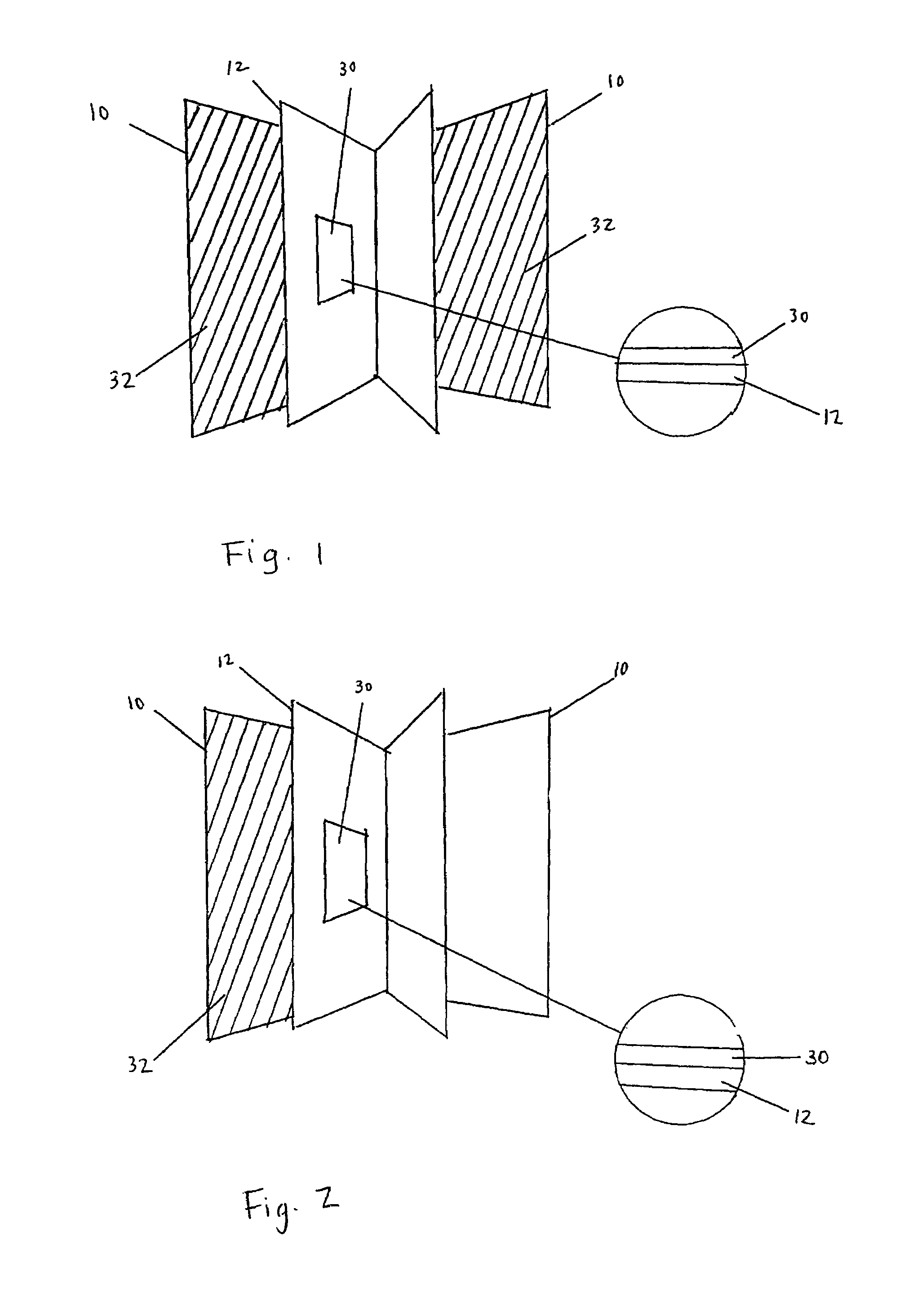
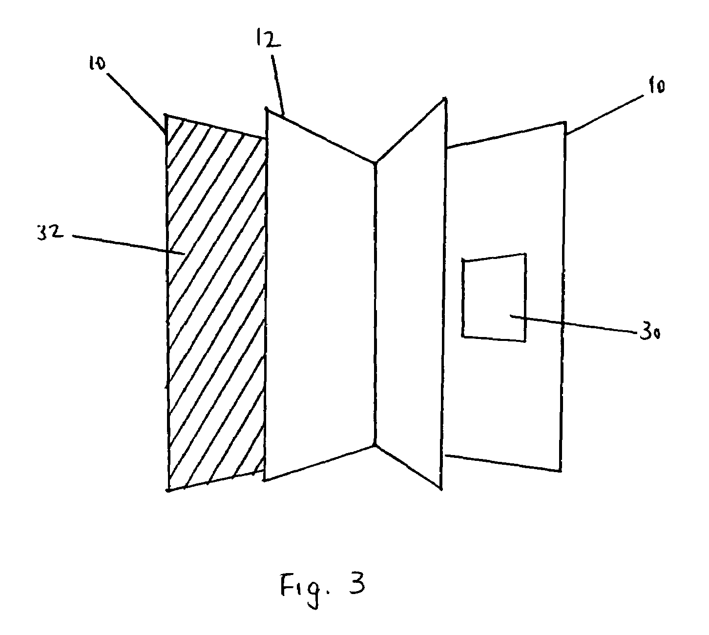
[0015]In one contemplated embodiment, the device is configured in a book-like fashion where one shield is on a page or cover and can open and close to selectively enable or disable the RFID tag located on a different page or cover of the passport or book. When the book or passport is closed, the shield and tag are in parallel planes and the tag reading is disabled. When the book or passport is open, the shield and tag are separated and in non-parallel planes, thereby allowing the tag to be read.
[0020]In still further preferred embodiments, the preferred two-part assembly has strong adhesives on both sides to adhere to opposing pages in a passport or book. The contemplated method comprises inserting the assembly between opposing pages and then closing the passport or book, thereby ensuring adhesion of the assembly to pages on both sides of the assembly. Then, by opening the passport or book, the two parts of the assembly detach from each other. The first part remains adhered onto one page while the second part remains adhered to a corresponding position on the opposing page. Whenever the passport or book closes, the assembly effectively realigns and reading of the tag is disabled (and where two conductive shields and a spacer layer is present, the realignment forms a sandwiched configuration, protecting the RFID tag in the middle from being surreptitiously read). This two-part assembly provides relatively easy and fast installation of RFID tags along with corresponding shields onto a passport or book.

Problems solved by technology

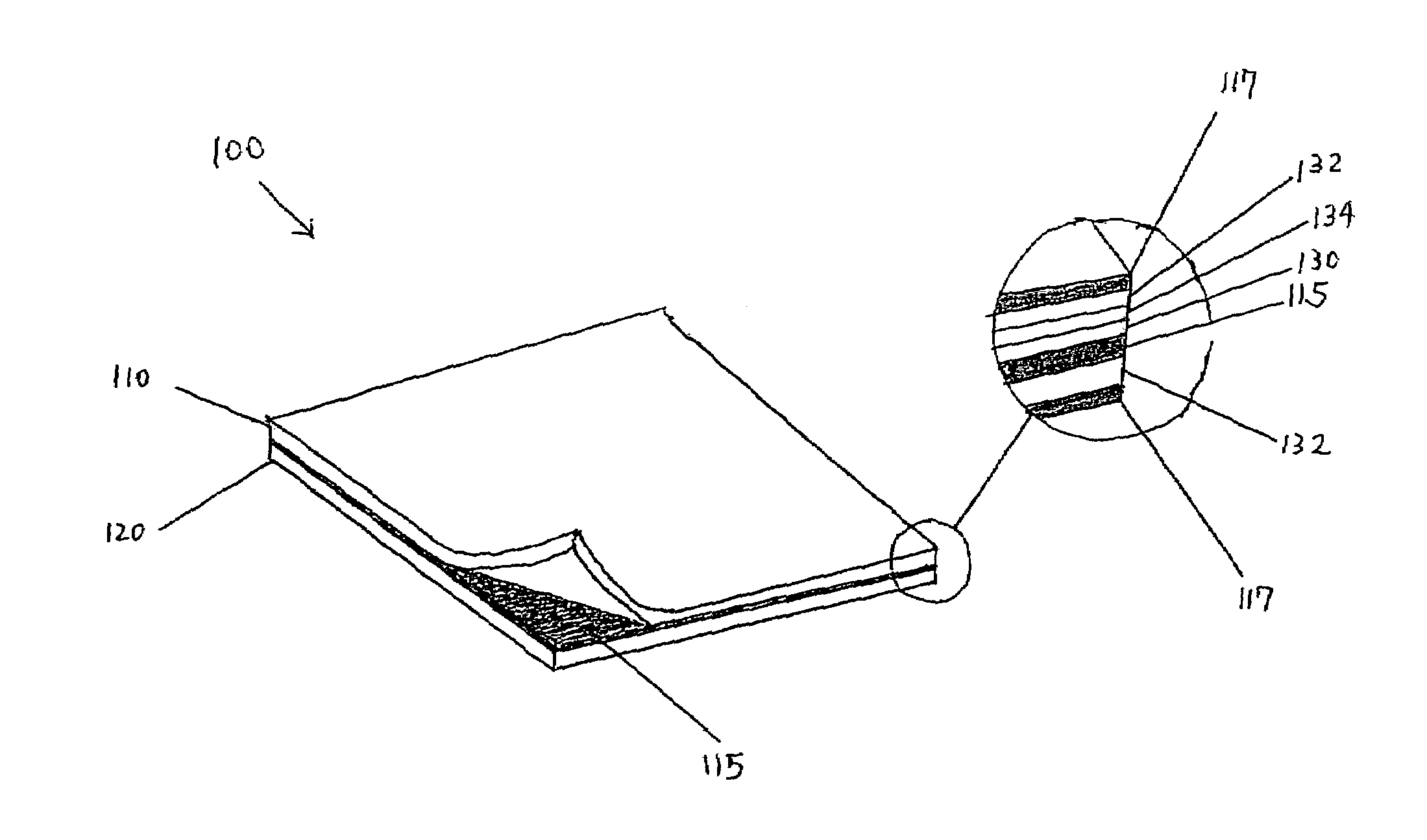
Without the spacer, a RFID tag layered directly on a conductor would not be able to be read.

Method used


Image

  • RFID security system and methods
  • RFID security system and methods
  • RFID security system and methods

Examples


Embodiment Construction

[0029]The invention and its various embodiments can now be better understood by turning to the following detailed description of the preferred embodiments, which are presented as illustrated examples of the invention defined in the claims. It is expressly understood that the invention as defined by the claims may be broader than the illustrated embodiments described below.

[0030]Many alterations and modifications may be made by those having ordinary skill in the art without departing from the spirit and scope of the invention. Therefore, it must be understood that the illustrated embodiment has been set forth only for the purposes of example and that it should not be taken as limiting the invention as defined by the following claims. For example, notwithstanding the fact that the elements of a claim are set forth below in a certain combination, it must be expressly understood that the invention includes other combinations of fewer, more or different elements, which are disclosed here...


PUM


Abstract

A Radio Frequency Identification (RFID) tag security device that selectively enables the readability of a RFID tag in a passport or book. The device has an RFID tag on one page and at least one layer of conductive material on a different page such that the tag and conductor are in parallel planes when the book or passport is closed and separated when it is open. Multiple conductors may be used on covers or pages surrounding the tag such that the tag is sandwiched between conductive materials when the book or passport is closed and loose when the book or passport is open. Optionally, the tag can be coupled to one of the conductive layers with a spacer placed between the tag and conductor. A two-part RFID tag assembly is also disclosed to have strong adhesives on both sides and weak bonds to detachably couple the two parts together.

Description

CROSS-REFERENCE TO RELATED APPLICATIONS[0001]This application claims priority from U.S. Provisional Patent Application No. 60 / 671,790, filed on Apr. 14, 2005, which is hereby incorporated by reference in its entirety.FIELD OF THE INVENTION[0002]The field of the invention is RFID security.BACKGROUND OF THE INVENTION[0003]Radio Frequency Identification (RFID) is an automatic identification method and technology, which relies on storing and remotely retrieving data by using devices called RFID tags or transponders. An RFID tag is a small object that can be attached to or incorporated into a product, animal, or person. RFID tags contain circuits and antennas to receive and respond to radio-frequency queries from an RFID transceiver.[0004]A minimal RFID system usually consists of at least a tag and a tag reader. The purpose of the RFID system is to transmit data to and from a mobile device, called a tag, which is read by an RFID reader and processed according to the needs of a particular...

Claims


Application Information

Patent Timeline
Patent Type & Authority Patents(United States)
IPC IPC(8): G08B13/14
CPCG06K19/07327
Inventor MAHAFFEY, KEVIN
Owner LOOKOUT MOBILE SECURITY
Why Eureka
Try Eureka