Reed drive of a loom

a loom and loom technology, applied in the direction of weaving, woven fabrics, textiles and paper, etc., can solve the problems of vibration problems, torsional and flexural stress on the drive shaft, etc., and achieve the effect of reducing the energy requiremen

Inactive Publication Date: 2009-01-27
LINDAUER DORNIER GMBH
View PDF25 Cites 0 Cited by
  • Summary
  • Abstract
  • Description
  • Claims
  • Application Information

AI Technical Summary

Benefits of technology

[0005]The aim of the invention is to develop further the reed drives according to the prior art and to provide a low-inertia dynamic drive with reduced energy requirement, which, overall, ensures a rigid construction and, moreover, a further decoupling of disturbance variables.

Problems solved by technology

It is also already pointed out that the torsional and flexural stress on the drive shaft presents a problem, as do inertia forces and the risk of vibration problems.

Method used


Image

  • Reed drive of a loom
  • Reed drive of a loom
  • Reed drive of a loom

Examples


Embodiment Construction

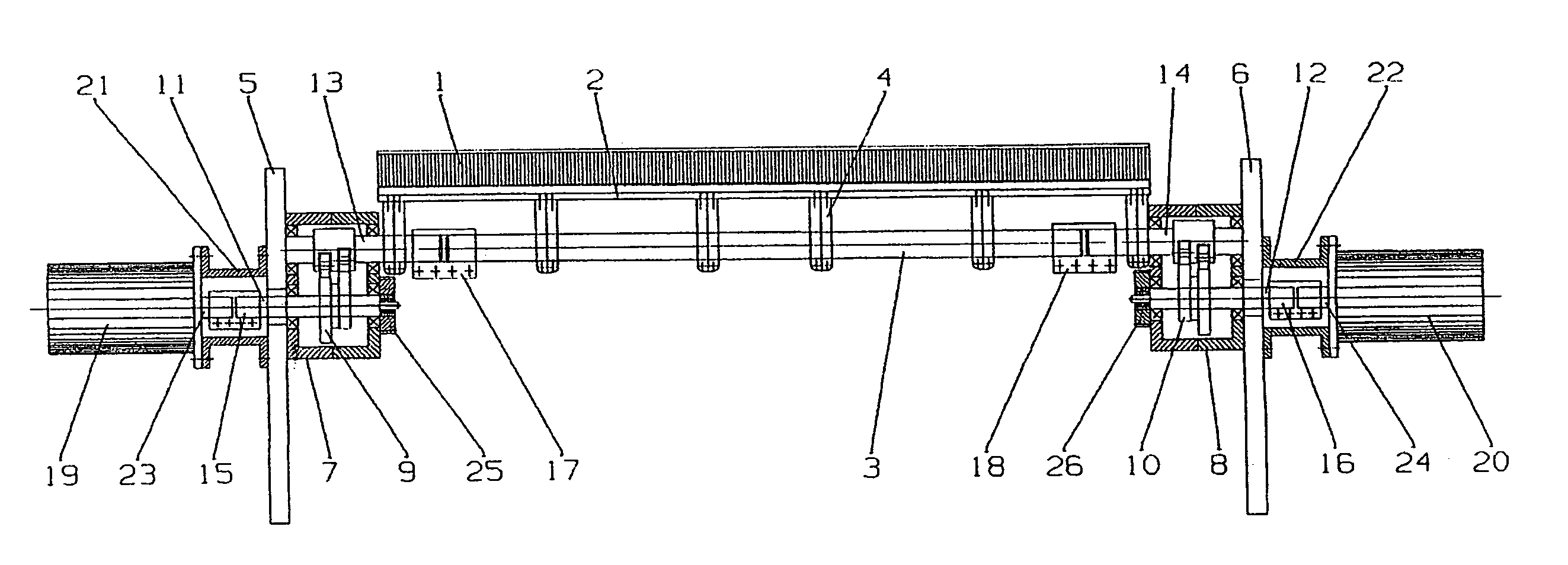
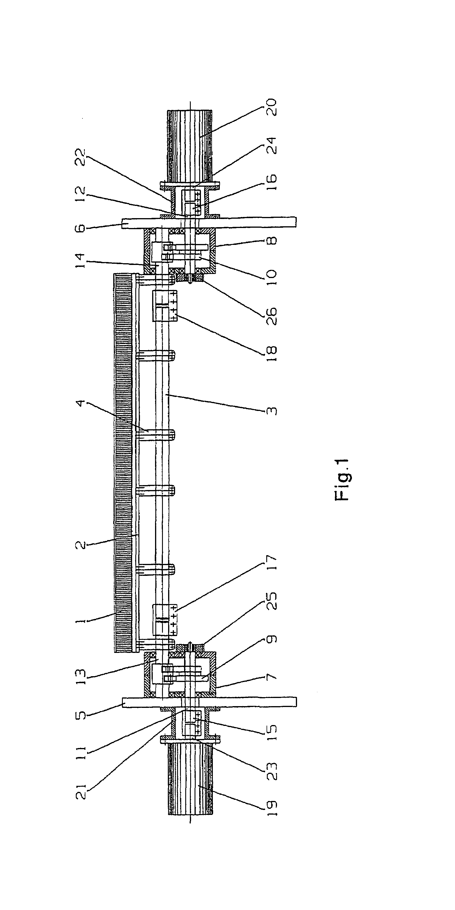
[0047]FIG. 1 illustrates a reed drive according to the invention in a diagrammatic view transversely to the take-off direction of the woven fabric obtained. The reed, which has a reed batten 2, is designated by 1. The reed batten 2 is connected to a reed shaft 3 via fastening arms 4, so that the reed shaft 3 is mounted on or connected to the reed 1 (or vice versa) . In the exemplary embodiment according to FIG. 1, the reed 1 and the reed batten 2 are in each case designed continuously in one part over the entire weaving width. The reed shaft 3, too, is of continuous design and extends almost over the entire weaving width.

[0048]The loom, not illustrated any further, has two fixed columns 5 and 6, on which two conversion gears, designated as a whole by 7 and 8, are located. In each conversion gear 7, 8 are located cam disks 9, 10, via which input members 11, 12 of the conversion gears 7, 8 are connected operatively to output members 13, 14 which are likewise arranged in the conversion...


PUM


Abstract

A reed drive of a loom includes a reed shaft connected to a reed. A conversion gearing having an input element and an output element is provided at each end of the reed shaft. The input elements are coupled to driven shafts of electromotive rotary drives to produce a common rotational motion with the same rotational speed as the driven shafts. The conversion gearings convert the rotating motion of their input elements into a reversible rotation of the output elements, and the output elements are coupled to the reed shaft in a rotationally fixed manner. Thus, the number of complete rotations of an input element is equal to the number of complete motion cycles of the reed shaft per unit of time.

Description

TITLE OF THE INVENTIONFIELD OF THE INVENTION[0001]The invention relates to a reed drive of a loom, with a reed mounted on a reed shaft and with conversion gears, by means of which the rotational movement of one or more electromotive rotary drives is converted into a reciprocating pivoting movement of the reed.BACKGROUND INFORMATION[0002]In the prior art, proposals have for some considerable time been noted to replace the central drive of looms by means of a single drive motor by a plurality of individual drives, each of which is drive-active in a very specific part region of the loom. So that these individual electromotive rotary drives cooperate appropriately during the weaving operation, synchronizing devices in the manner of electric shafts are required and are known. The invention is concerned particularly with the individual drive of the reed.[0003]Examples of this may be gathered from EP 796 360 B1 and EP 1 312 709 A1. According to EP 796 360 B1, the reed has mounted on or con...

Claims


Application Information

Patent Timeline
Patent Type & Authority Patents(United States)
IPC IPC(8): D03D49/06D03D49/60D03D13/00D03D51/02
CPCD03D49/60
Inventor KRUMM, VALENTINVON ZWEHL, DIETMARLEHMANN, MICHAELLAUKAMP, THOMAS
Owner LINDAUER DORNIER GMBH
Why Eureka
Try Eureka