Plant and a method for increased oil recovery

a technology of oil recovery and plant, applied in the field of natural gas, can solve problems such as the formation of explosive gases, and achieve the effect of increasing oil recovery

Inactive Publication Date: 2009-01-27
DEN NORSKE STATS OLJESELSKAP AS
View PDF22 Cites 170 Cited by
  • Summary
  • Abstract
  • Description
  • Claims
  • Application Information

AI Technical Summary

Benefits of technology

[0020]injecting the nitrogen-rich fraction and at least a part of the waste gas into the oil reservoir to increase the oil recovery from the reservoir.
[0034]By combining a plant for production of high-purity nitrogen with the production of oxygen, the co-producing air separation unit only becomes 10-20% more expensive than an air separation unit that only produces high-purity nitrogen for injection into oil fields. This allows significant cost savings, both for production of synthesis products such as methanol and synthetic fuel, and for oil field injection.

Problems solved by technology

A too-high ratio may lead to the formation of an explosive gas.

Method used


Image

  • Plant and a method for increased oil recovery
  • Plant and a method for increased oil recovery
  • Plant and a method for increased oil recovery

Examples


example 1

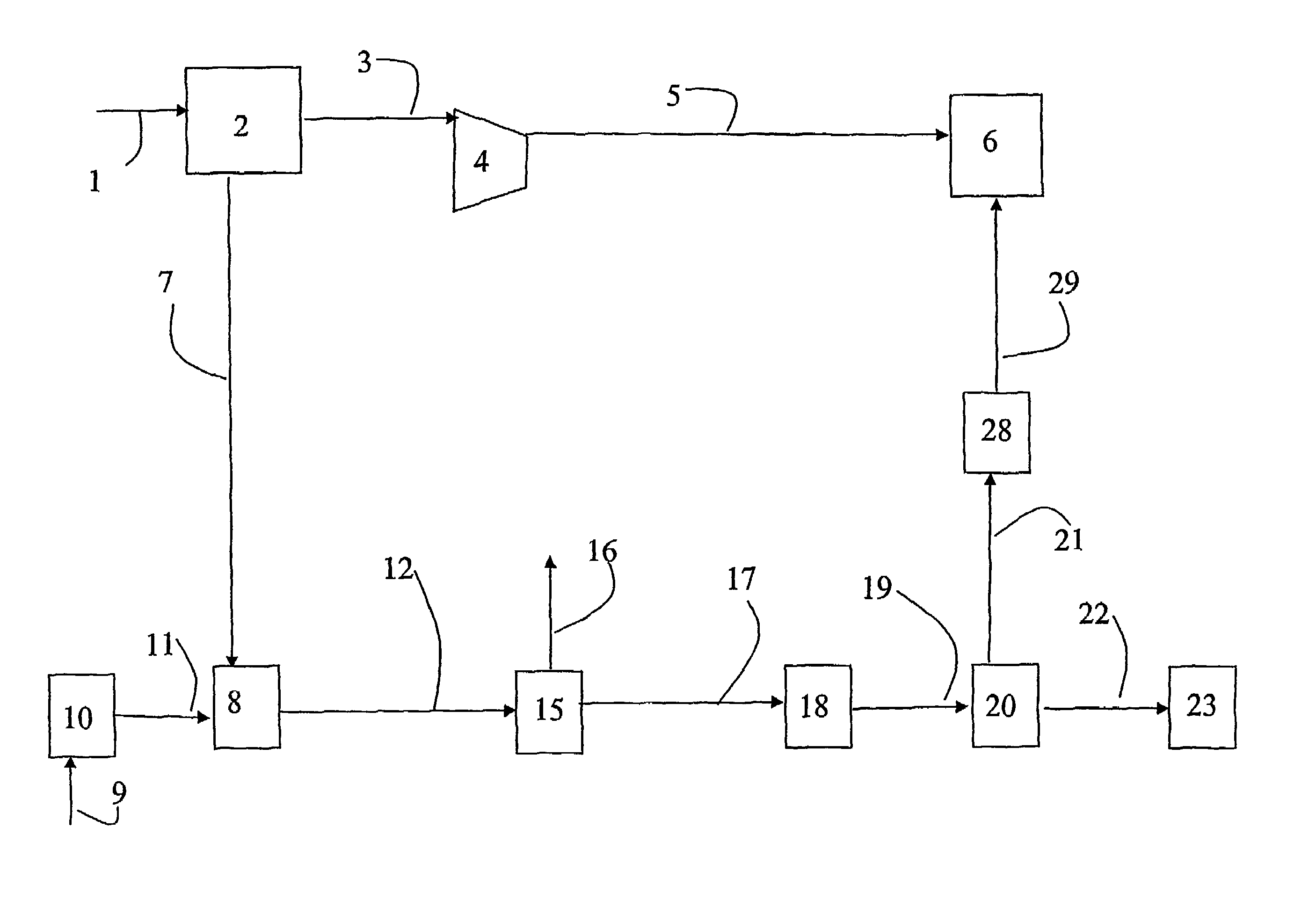
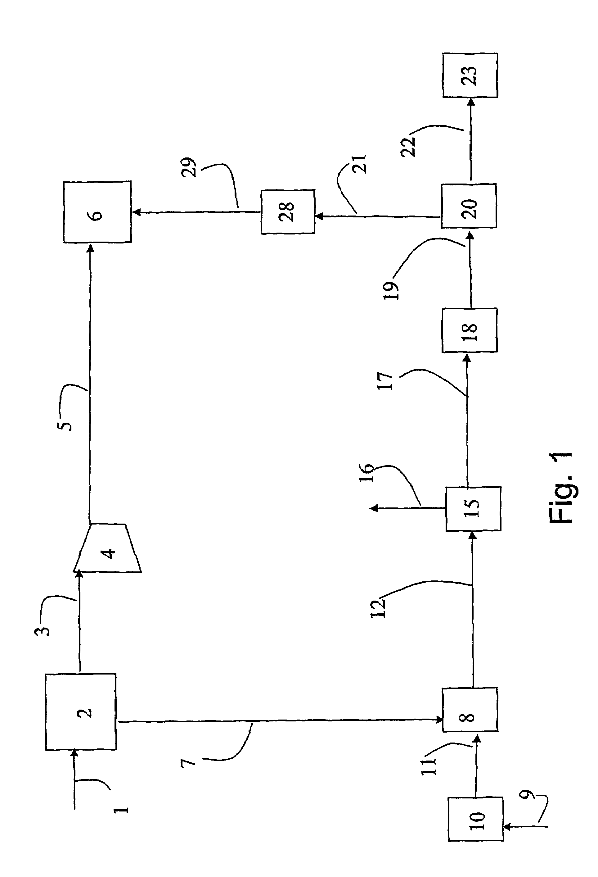
[0122]Calculations have been carried out for a plant according to FIG. 1 for production of methanol, which in addition comprises a bypass line that leads some of the synthesis gas in line 12 past the synthesis unit 15 and on to line 17.

[0123]The air separation unit can deliver 38 400 MTPD N2 and 6400 MTPD O2. This air separation unit requires approximately 115 MW of power, which is delivered in the form of high-pressure steam from the synthesis gas section.

[0124]The nitrogen is extracted at 3 bar and 0 degrees C. The gas is compressed to 220 bar for injection. Compression requires approximately 304 MW.

[0125]The oxygen can be fed to an autothermal reformer for production of synthesis gas from natural gas. The process operates with a steam / carbon ratio of 0.6. The temperature and pressure at the outlet from the ATR is 1030 degrees Celsius and 45 bar, respectively. See Table 1 for the natural gas composition. Note, all compositions are given on a dry basis, i.e. without water.

[0126]

TAB...

example 2

[0134]A simulation on a plant as illustrated in FIG. 4 was performed. 367 000 Sm3 / hr natural gas from line 9 was mixed with 183 t / h steam from line 50 in order to reach steam to carbon ratio of 0.6. The mixture was preheated to 600° C. and fed to an auto-thermal reformer (ATR) 8.275 t / hr oxygen (6600 MTPD) was introduced into the ATR 8 from the line 7. The outlet temperature from the ATR 8 was 1030° C. The amount of oxygen consumed in the ATR corresponds to a co-production of N2 of 39600 MTPD.

[0135]The syngas leaving the ATR 8 through line 12, which is in equilibrium and at a temperature of around 1030° C., is cooled to about 350° C. with evaporating water in the syngas cool down unit 52 producing about 830 t / h saturated 110 bar steam that is withdrawn in line 54. The steam in line 54 may be utilized for EOR as illustrated in FIG. 4, or in turbines to generate power.

[0136]After the syngas has been cooled down 178 t / h decant water is removed and about 60 000 Sm3 / hr hydrogen (hydrogen...


PUM

PropertyMeasurementUnit
pressureaaaaaaaaaa
pressureaaaaaaaaaa
outlet temperatureaaaaaaaaaa

Abstract

A method for increasing oil recovery from an oil reservoir by injection of gas into the reservoir, is described. The method comprises separation of air into an oxygen-rich fraction and a nitrogen-rich fraction, reformation of natural gas together with oxygen to produce a synthesis gas for production of methanol or other oxygenated hydrocarbons or higher hydrocarbons. The raw synthesis products and a waste gas from the synthesis are separated, and the nitrogen-rich fraction and at least a part of the waste gas are injected into the oil reservoir to increase the oil recovery from the reservoir. A plant for performing the method is also described.

Description

CROSS REFERENCE TO RELATED APPLICATIONS[0001]This application is based on International Application No. PCT / NO03 / 00416, filed 12 Dec. 2003, having an International Publication Number of WO 2004 / 055323 A1 and an International Publication Date of 1 Jul. 2004, which is based on Norwegian Patent Application No. 2002 6021, filed 13 Dec., 2002.THE FIELD OF THE INVENTION[0002]The present invention regards the use of natural gas in the development of industry and oil fields. In particular, the invention regards a method and a plant for integrated production of synthesis gas for synthesis of higher hydrocarbons or oxygenated hydrocarbons and gas for injection into an oil reservoir.THE BACKGROUND OF THE INVENTION[0003]Injection of various gases into an oil reservoir in order to enhance the oil recovery from the reservoir, and to stabilize it, has long been known and used. Gases such as CO2, N2 and natural gas will reduce the surface tension between gas and oil, and thus contribute to both inc...

Claims


Application Information

Patent Timeline
Patent Type & Authority Patents(United States)
IPC IPC(8): E21B43/18E21B43/24E21B43/16E21B43/40F25J3/04
CPCE21B43/168E21B43/40F25J3/04539F25J3/04569F25J3/04575F25J3/04593C01B3/384C01B2203/0233C01B2203/0816C01B2203/061C01B3/36C01B2203/062
Inventor OLSVIK, OLARYTTER, ERLINGSOGGE, JOSTEINSTENSEN, JAN AGE
Owner DEN NORSKE STATS OLJESELSKAP AS
Why Eureka
Try Eureka