Equipment security apparatus

a technology for security apparatus and equipment, applied in the field of equipment security apparatus, can solve the problems of reducing the ability of projectors, limiting the access to various control buttons and signal input/output connections, and often stealing devices

Inactive Publication Date: 2009-01-27
BUSINESS MACHINE SECURITY
View PDF42 Cites 25 Cited by
  • Summary
  • Abstract
  • Description
  • Claims
  • Application Information

AI Technical Summary

Benefits of technology

[0014]As summarized above, and as discussed more fully below, the present invention provides several advantages. For example, the fastening volume, in which the fasteners that connect the electronic device to the tray and the fasteners that connect the swivel mechanism to the column, is not accessible. This greatly enhances the security of the apparatus because a thief is unable to tamper with the fasteners without first defeating the lock. Another advantage of the present invention is that, while the fasteners are inaccessible to a thief, the electronic device is substantially accessible to the user. This accessibility makes the electronic device easier to operate compared to other systems that mostly or completely enclose the electronic device. Another advantage of the present invention is that a wide variety of electronic devices, e.g., devices of differing sizes, devices having different mounting hardware placement, etc., can be used without requiring a wide range of adapter configurations. Another advantage is provided by the swivel mechanism which allows orientation of the electronic device, while having a relatively simple design. This simple swivel mechanism design is easily adjusted and thus the electronic device can be oriented by a one person.

Problems solved by technology

Being valuable and relatively portable, such devices are often a target for theft.
The cage, however, tends to unduly limit access to the various control buttons and signal input / output connections located on the projector's outside surface.
In addition, the cage tends to reduce the ability of the projector to eliminate the heat generated during operation of the projector.
The size of the cage also limits the size of the projector that can be secured.
This base unit style mounting device is not convenient for several reasons.
In addition, the separate adjustment of pitch, roll, and yaw is tedious and difficult because the projector must be held in place while many fasteners are tightened.
However, because these fasteners are accessible to a would-be thief, they still can be removed relatively easily by an experienced thief.

Method used


Image

  • Equipment security apparatus
  • Equipment security apparatus
  • Equipment security apparatus

Examples


Embodiment Construction

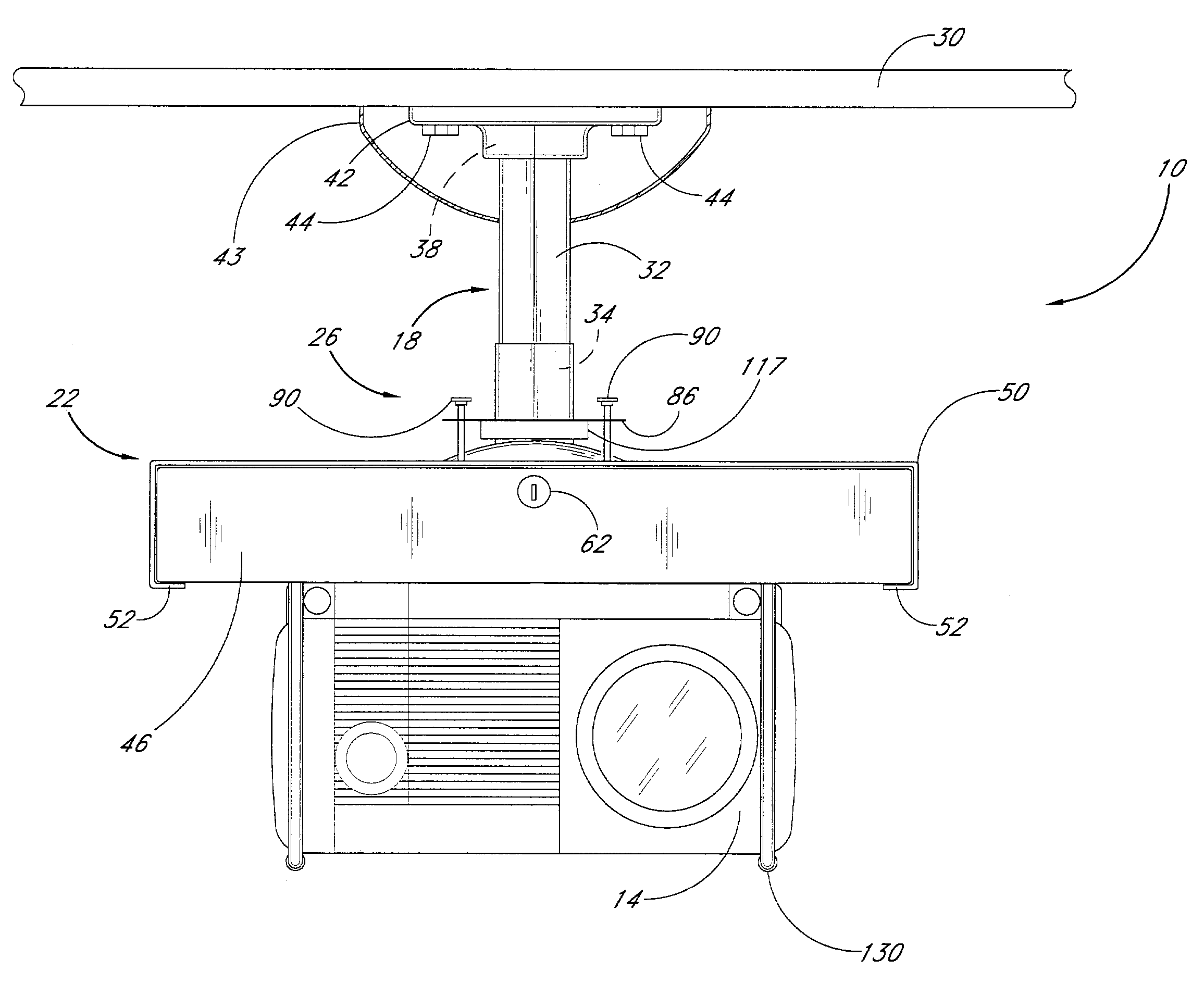
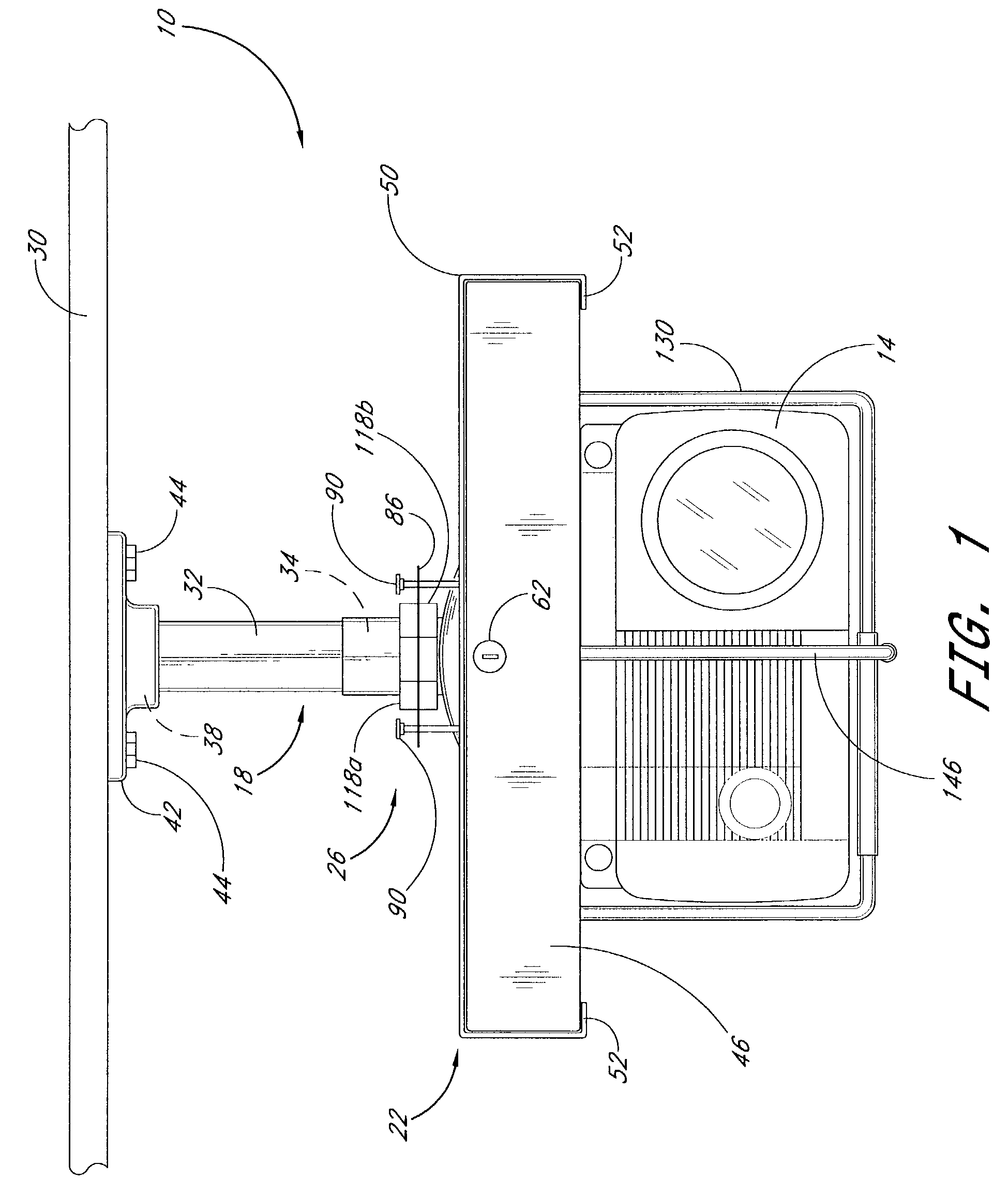
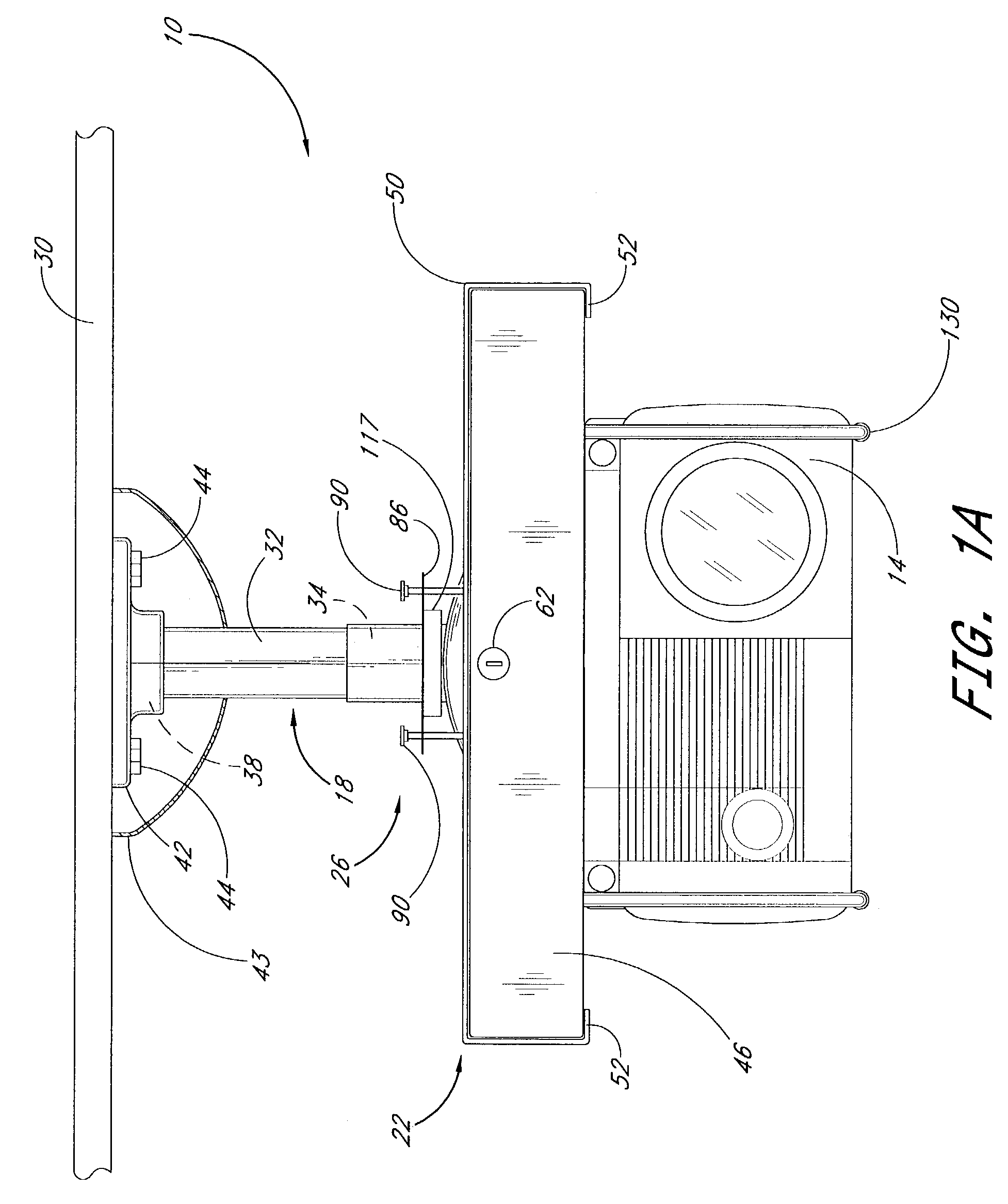
[0029]FIG. 1 is a front elevation view of a security apparatus 10 for securing a liquid crystal display (LCD) projector 14 against theft. The security apparatus 10 includes a structural mount 18, a security enclosure 22, and a swivel mechanism 26. The security enclosure 22 engages the projector 14 in a manner that protects the projector 14 from theft, as discussed more fully below. The security enclosure 22 also engages the swivel mechanism 26, which adjusts the orientation of the projector 14 with respect to a structure 30 or to a projection surface, such as a projection screen. The configuration and operation of the swivel mechanism 26 is discussed in more detail below in connection with FIGS. 4-7. The structural mount 18 is connected to the swivel mechanism 26 and is also connected to the structure 30. The structure 30 may broadly be any structure that is substantially larger than the projector 14. For example, as discussed in more detail below, the structure may be, without limi...


PUM


Abstract

A security apparatus connects an electronic device to a structure. The security apparatus includes a structural mount, a security enclosure, and a swivel mechanism. The structural mount extends from the structure. The security enclosure has a tray that can mount a variety of electronic devices externally to the security enclosure. The security enclosure also has a security housing that slidably receives the tray. The tray and the security housing define a substantially secure fastening volume wherein at least one electronic device fastener is located. The swivel mechanism, which is at least partially located within the fastening volume, engages the security housing and orients the security enclosure and the electronic device attached thereto with respect to the structure.

Description

RELATED APPLICATION[0001]This application claims the benefit of U.S. Provisional Application No. 60 / 391,396, filed Jun. 24, 2002 and U.S. Provisional Application No. 60 / 415,695, filed Oct. 2, 2002, the contents of both of which are hereby expressly incorporated by reference herein.BACKGROUND OF THE INVENTION[0002]1. Field of the Invention[0003]The present invention generally relates to an apparatus for mounting equipment in a public building or the like, and, more particularly, to an equipment security apparatus for securing equipment from theft.[0004]2. Description of the Related Art[0005]Electronic devices, such as projectors, are often used in public buildings for communicating information to the building's users. Such electronic devices typically include a power cord, control buttons and signal input / output connections, which are usually located around the outside surface of the devices. The control buttons control the performance and other aspects of the devices, while the powe...

Claims


Application Information

Patent Timeline
Patent Type & Authority Patents(United States)
IPC IPC(8): F16M13/00E05B73/00F16M11/14F16M13/02
CPCE05B73/0082F16M11/14F16M13/02F16M13/027F16M2200/022Y10T70/5009Y10T70/5027
Inventor UMBERG, JOHN R.
Owner BUSINESS MACHINE SECURITY
Why Eureka
Try Eureka