Method for monitoring a drive device for a standstill condition, monitoring system therefore, and drive system therefore

a drive device and standstill technology, applied in the direction of computer control, program control, emergency protective arrangements for automatic disconnection, etc., can solve the problem that the abovementioned sensor fault cannot be detected

Active Publication Date: 2009-01-27
SIEMENS AG
View PDF17 Cites 12 Cited by
  • Summary
  • Abstract
  • Description
  • Claims
  • Application Information

AI Technical Summary

Benefits of technology

[0008]The object of the present invention consists in providing a method for monitoring a drive device for a standstill condition and corresponding devices, by means of which the abovementioned faults can also reliably be de

Problems solved by technology

The problem that the abovementioned sensor faults cannot be detected only occurs

Method used


Image

  • Method for monitoring a drive device for a standstill condition, monitoring system therefore, and drive system therefore
  • Method for monitoring a drive device for a standstill condition, monitoring system therefore, and drive system therefore
  • Method for monitoring a drive device for a standstill condition, monitoring system therefore, and drive system therefore

Examples


Embodiment Construction

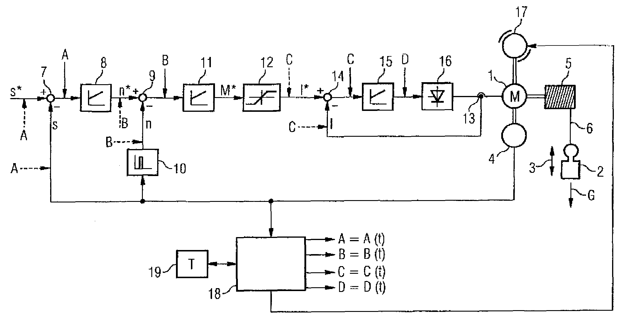
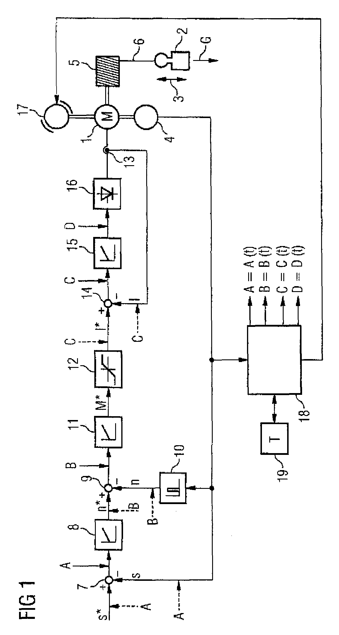
[0026]As shown in FIG. 1, a drive system has a drive device 1. In this case, the drive device 1 is preferably in the form of an electrical drive device 1. It is used for moving a movable element 2. This is indicated in FIG. 1 by an arrow 3. The movable element 2 can in this case in particular be in the form of a load 2, which can be moved against the force of gravity and exerts a force due to weight G on the drive device 1. This is illustrated in FIG. 1 by the configuration of the movable element 2 as a schematically indicated weight.

[0027]Furthermore, the drive system has a sensor device 4. The sensor device 4 in the context of the drive system according to the invention is preferably the only sensor device 4 provided. In its correct state it is connected to the drive device 1 such that it is fixed against rotation.

[0028]By means of the sensor device 4, an actual position s of the drive device 1 is detected, and a corresponding sensor output signal is output. Alternatively, given a...


PUM


Abstract

In a method for monitoring a stationary condition of a drive device, a monitoring device provides the drive device with a temporally varying monitoring signal which, when a sensor device connected to the drive device functions properly, modulates a sensor output signal of the sensor device in accordance with the monitoring input signal. The monitoring device receives the sensor signal and monitors it for the presence of a corresponding signal component. In the absence of such a signal component, the monitoring device controls a safety device which converts the drive device into a safe state. When the drive device is controlled by means of at least two phase-shifted current regulators, it is possible for the monitoring device to monitor an output signal of at least one of the current regulators for constancy and to control the safety device when the output signal of the at least one current regulator changes.

Description

BACKGROUND OF THE INVENTION[0001]The present invention relates to a method for monitoring a drive device for a standstill condition.[0002]There are machine parts (for example an inclined bed in the case of a rotary machine or a lift cage in the case of normal conveying equipment) which are driven by means of conventional electrical drive devices and in which the state “suspended load” can occur. That is to say there is a state in which a minimum torque needs to be applied by the drive in order to counteract the force of gravity, which pulls the load downwards.[0003]In the event of failure of or another fault in the electrical drive device, said electrical drive device cannot apply the required torque. If no further measures were to be taken, the lift cage could fall down, for example, and people and objects may be endangered.[0004]In order to provide protection against such risks, safety devices are known, for example releasable brakes, which engage in the event of a fault and in th...

Claims


Application Information

Patent Timeline
IPC IPC(8): H02P3/16
CPCG05B19/19G05B19/4062B66B5/0031
Inventor HAHN, ULRICHSCHWESIG, GUNTER
Owner SIEMENS AG
Why Eureka
Try Eureka