
Developer container, process cartridge, image forming apparatus and manufacturing method for developer container

a technology of developer containers and process cartridges, which is applied in the direction of electrographic process devices, instruments, optics, etc., can solve the problems of gaps between the sealing sheet and the end seal, and failure to be completely plugged

Active Publication Date: 2009-01-27
CANON KK
View PDF23 Cites 56 Cited by
  • Summary
  • Abstract
  • Description
  • Claims
  • Application Information

AI Technical Summary

Benefits of technology

The present invention aims to prevent developer from leaking and oozing out of a container. It provides a developer container with a rotatable member, a container body, a sealing member, a sheet, a gap, a communication hole, and packing material. The process cartridge detachably mountable to an image forming apparatus includes an image bearing member, a cleaning member, a container body, a sealing member, a sheet, a gap, a communication hole, and packing material. The method includes preparing a container body, mounting a sealing member, mounting a sheet, and injecting packing material. The technical effects of the invention include preventing developer leakage and oozing out.

Problems solved by technology

When the cleaning apparatus is assembled, gaps are created between the end seals and the surfaces of the cleaning apparatus frame, because of the errors in the shape of the end seal, the errors in the step for pasting the end seals, and / or the like.
However, the above described structural arrangement, which is based on the prior art, is problematic in that if the amount by which filler / sealer is filled into the gaps between the end seals and cleaning apparatus frame to plug them is small, the gaps fail to be completely plugged.
On the other hand, if the amount is large, the filler / sealer pushes up the sealing sheet, creating thereby gaps between the sealing sheet and end seals.

Method used


Image

  • Developer container, process cartridge, image forming apparatus and manufacturing method for developer container
  • Developer container, process cartridge, image forming apparatus and manufacturing method for developer container
  • Developer container, process cartridge, image forming apparatus and manufacturing method for developer container

Examples


embodiment 1

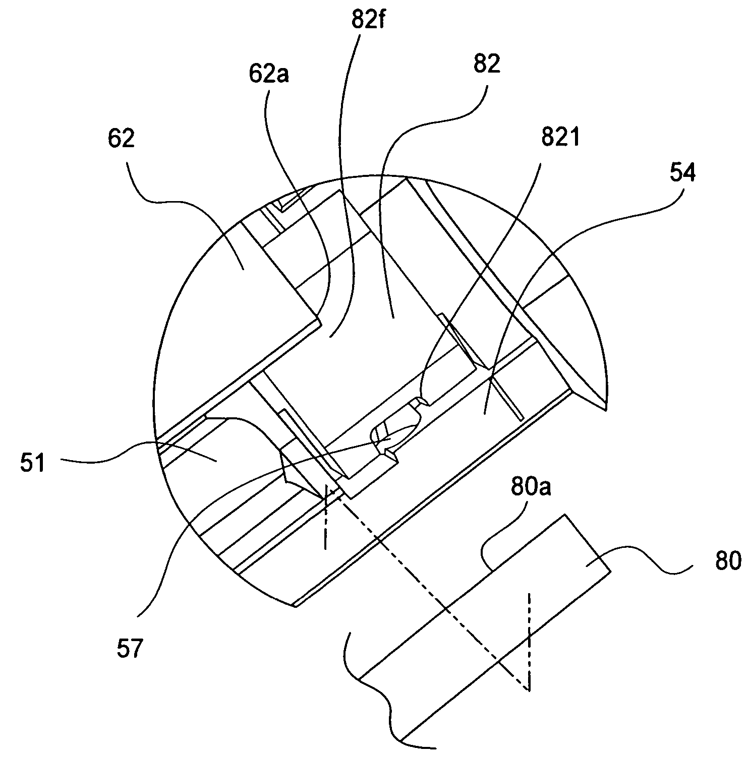
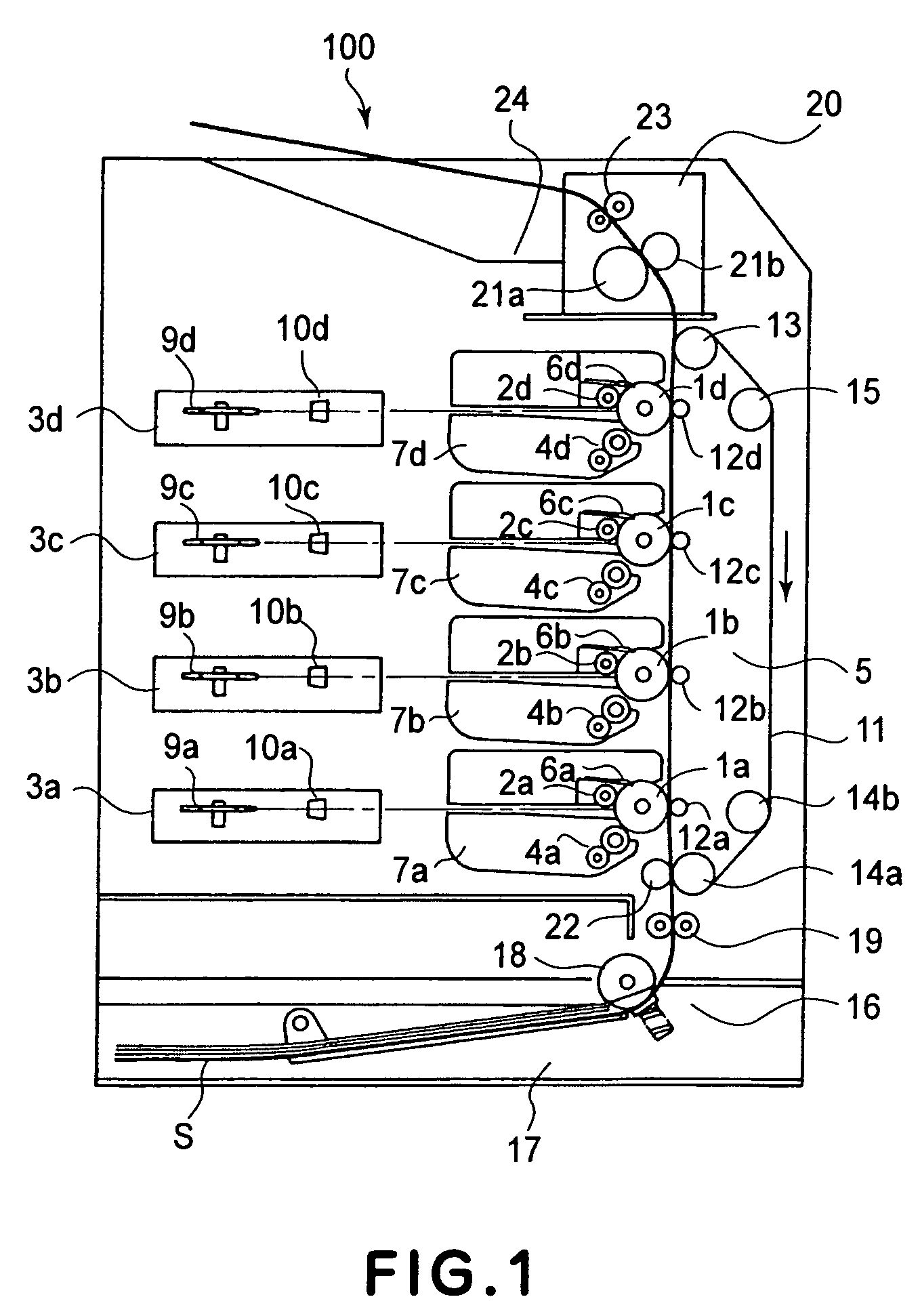
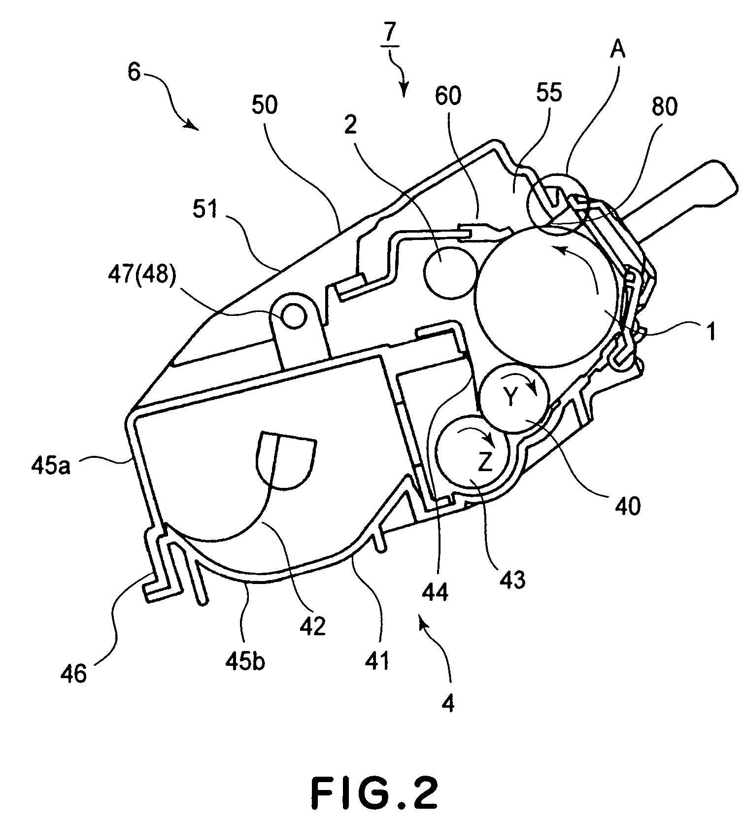
[0070]Next, referring to FIGS. 2, and 5-14, one of the preferred embodiments of the present invention will be described. FIG. 5 is a schematic perspective view of the cleaning apparatus, showing how the cleaning member is attached to the cleaner unit frame 51. FIG. 6 is a schematic perspective view of the cleaner unit 50. FIG. 7 is a schematic perspective view of the filler / sealer inlet of the cleaner unit frame 51. FIG. 8 is a schematic perspective view of one of the lengthwise end portions of the cleaner unit frame 51, and the corresponding end seal 82. FIG. 9 is a schematic front view of one of the lengthwise end portions of the cleaner unit frame 51, and the corresponding end seal 82. FIG. 10 is a schematic front view of one of the lengthwise end portions of the cleaner unit frame 51, and corresponding end seal 82. FIG. 11 is a schematic front view of one of the lengthwise end portions of the cleaner unit frame 51, the corresponding end seal 82, and the corresponding body of fil...


PUM


Abstract

A developer container for an image forming apparatus, said developer container including a rotatable member; a container body for containing a developer; a sealing member, provided in the container body, for preventing leakage of the developer out of the container body; a sheet, provided in the container body, for contacting the rotatable member to guide the developer into the container body; a gap provided between the container body and the sealing member and covered by the sheet; a communication hole provided in the container body in fluid communication with the gap; packing material filled in the gap through the communication hole for preventing leakage of the developer through the gap.

Description

FIELD OF THE INVENTION AND RELATED ART[0001]The present invention relates to a developer container, a cartridge, a process cartridge, an image forming apparatus, and a method for manufacturing a developer container.[0002]An image forming apparatus, such as a printer which employs an electrophotographic process, forms a latent image by uniformly charging a photosensitive drum as an image bearing member, and selectively exposing numerous points of the peripheral surface of the photosensitive drum. Then, the image forming apparatus develops the latent image into a visible image (image formed of toner, which hereafter will be referred to as toner image), with the use of developer, and transfers the toner image onto recording medium. Further, the image forming apparatus applies heat and pressure to the transferred toner image, whereby the toner image is fixed to the recording medium, concluding the image recording process of the image forming apparatus.[0003]An apparatus such as the abov...

Claims


Application Information

Patent Timeline
Patent Type & Authority Patents(United States)
IPC IPC(8): G03G15/08
CPCG03G15/0898G03G15/0875G03G2215/0685
Inventor UENO, TAKAHITOKAKITANI, MASAKI
Owner CANON KK
Learn More