Locking system, floorboard comprising such a locking system, as well as method for making floorboards

a locking system and locking system technology, applied in the direction of load-supporting elements, structural elements, building components, etc., can solve the problems of inability to achieve snap action, reduced height of locking elements, and increased difficulty in snapping action, so as to reduce the width of fibreboard strips, reduce material waste, and save costs

Inactive Publication Date: 2009-02-03
VÄLINGE INNOVATION AB
View PDF420 Cites 56 Cited by
  • Summary
  • Abstract
  • Description
  • Claims
  • Application Information

AI Technical Summary

Benefits of technology

[0027]Although the floor according to WO 9426999 and the floor sold under the brand name Fiboloc® exhibit major advantages in comparison with traditional, glued floors, further improvements are desirable mainly by way of cost savings which can be achieved by reducing the width of the fibreboard strip from the present 10 mm. A narrower strip has the advantage of producing less material waste in connection with the forming of the strip. However, this has not been possible since narrower strips of the Uniclic and Isilock type have produced inferior test results. The reason for this is that narrow strips require a small angle of the locking surface of the locking element in relation to the horizontal plane (termed locking angle) in order to enable the boards to be joined together by means of angling, since the locking groove follows an arc having its centre in the upper joint edge of the board. The height of the locking element must also be reduced since narrow strips are not as flexible, rendering snap action more difficult.
[0028]To sum up, narrow strips have the advantage that material waste is reduced, but the drawbacks that the locking angle must be small to permit angling and that the locking element must be low to permit joining by snap action.

Problems solved by technology

However, this has not been possible since narrower strips of the Uniclic and Isilock type have produced inferior test results.
The height of the locking element must also be reduced since narrow strips are not as flexible, rendering snap action more difficult.
Moreover, at present there are no known products or methods which afford adequate solutions to these problems which are related to(i) mechanical strength of the joint of floorboards with a mechanical locking system of the strip lock type;(ii) handling and laying of such floorboards;(iii) properties of a finished, joined floor made of such floorboards.

Method used


Image

  • Locking system, floorboard comprising such a locking system, as well as method for making floorboards
  • Locking system, floorboard comprising such a locking system, as well as method for making floorboards
  • Locking system, floorboard comprising such a locking system, as well as method for making floorboards

Examples


Embodiment Construction

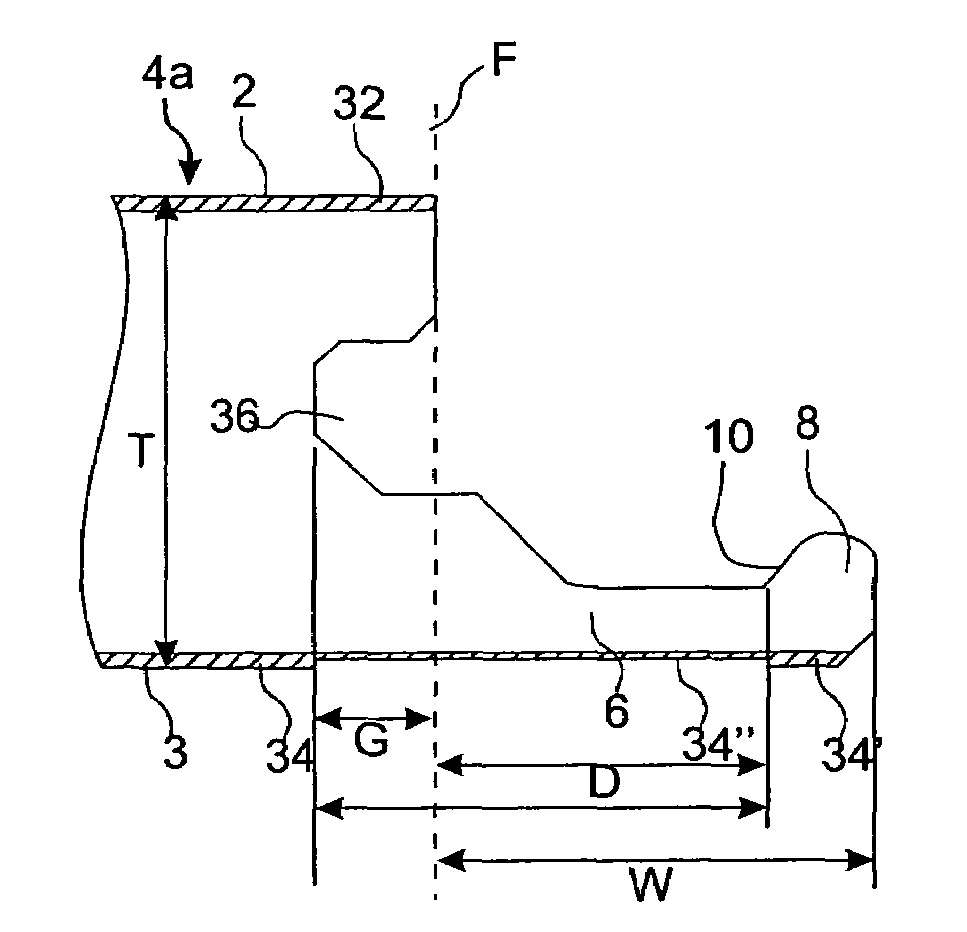
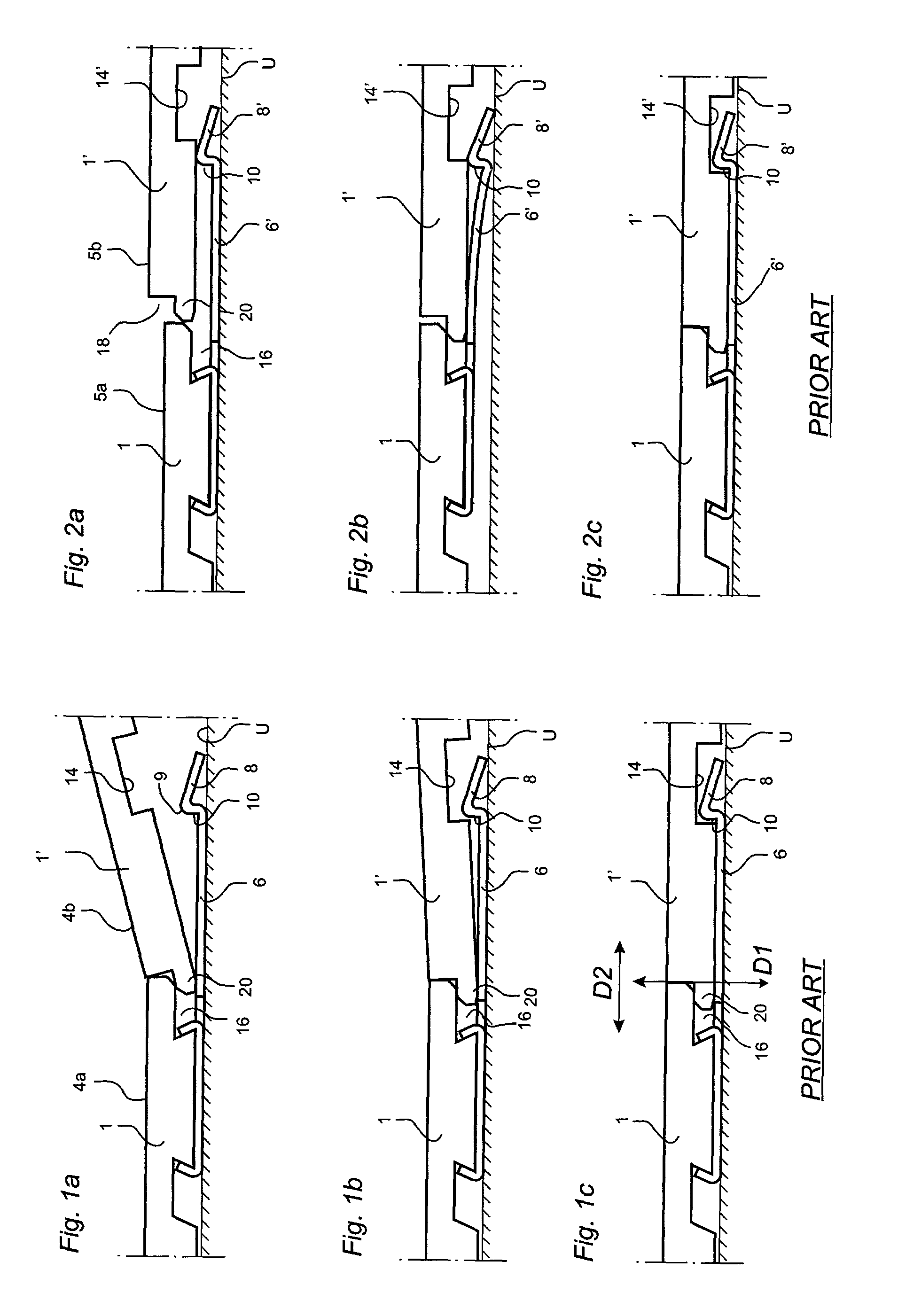
[0084]Prior to the description of preferred embodiments, with reference to FIGS. 5-8, a detailed explanation will first be given of the background to and the impact of strip-bending.

[0085]The cross-sections shown in FIGS. 5 and 6 are hypothetical, unpublished cross-sections, but they are fairly similar to “Fiboloc®” in FIG. 4a and “Uniclic” in FIG. 4b. Accordingly, FIGS. 5 and 6 do not represent the invention. Parts which correspond to those in the previous Figures are in most cases provided with the same reference numerals. The design, function, and material composition of the basic components of the boards in FIGS. 5 and 6 are essentially the same as in embodiments of the present invention and, consequently, where applicable, the following description of FIGS. 5 and 6 also applies to the subsequently described embodiments of the invention.

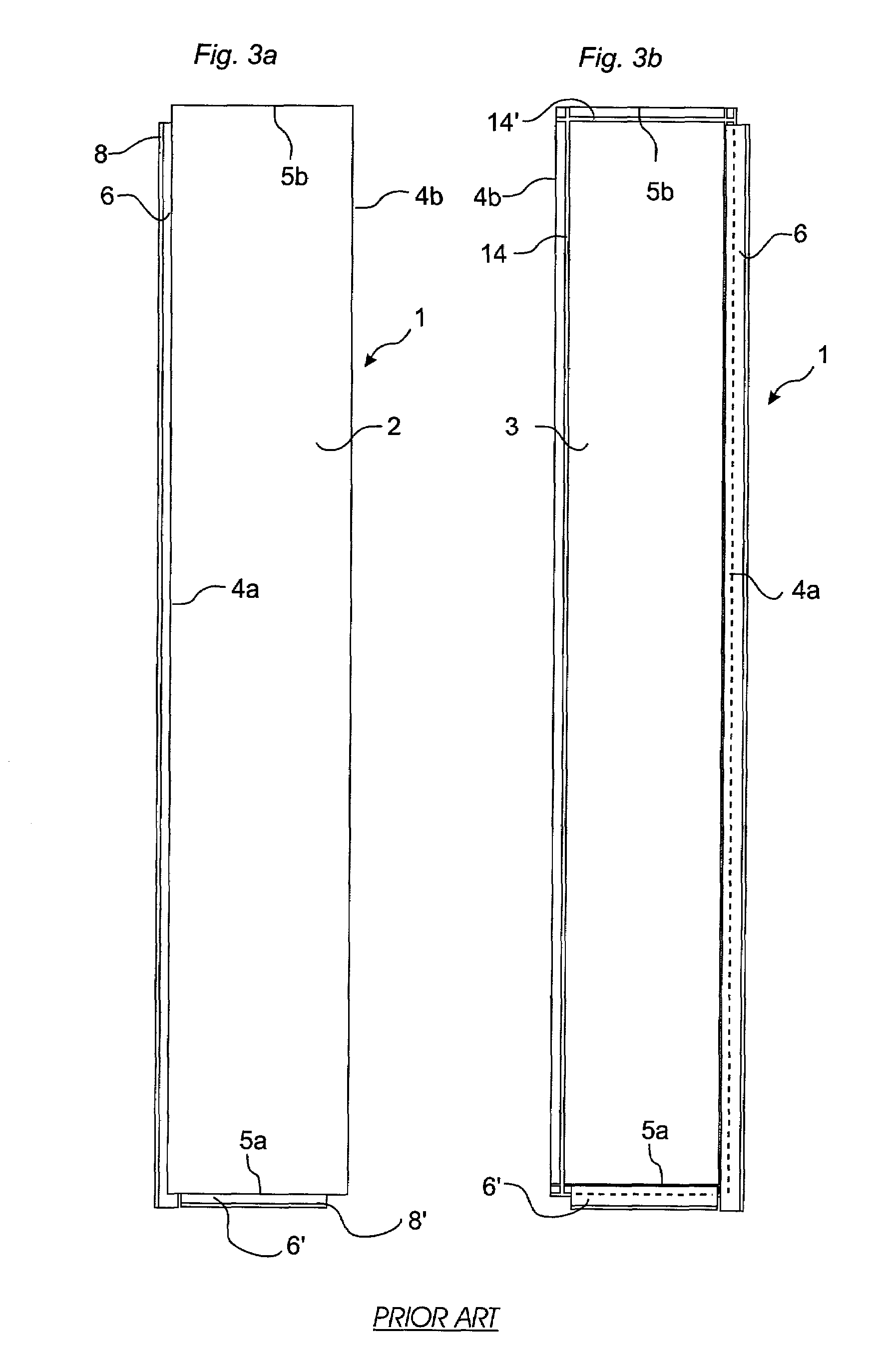
[0086]In the embodiment shown, the floorboards 1, 1′ in FIG. 5 are rectangular with opposite long sides 4a, 4b and opposite short sides 5a, 5b. ...


PUM


Abstract

The invention relates to a locking system for mechanical joining of floorboards (1) constructed from a body (30), a rear balancing layer (34), and an upper surface layer (32). A strip (6), which is integrally formed with the body (30) of the floorboard and which projects from a joint plane (F) and under an adjoining board (1), has a locking element (8) which engages a locking groove (14) in the rear side of the adjoining board. The joint edge provided with the strip (6) is modified with respect to the balancing layer (34), for example by means of machining of the balancing layer under the strip (6), in order to prevent deflection of the strip (6) caused by changes in relative humidity. The invention also relates to a floorboard provided with such a locking system, as well as a method for making floorboards with such a locking system.

Description

[0001]This application is a continuation of International Application No. PCT / SE00 / 00785 filed on Apr. 26, 2000, which International Application was published by the International Bureau in English on 9 Nov. 2000. The entire contents of PCT / SE00 / 00785 are hereby incorporated herein by reference.TECHNICAL FIELD[0002]The invention generally relates to the field of mechanical locking of floorboards. The invention relates to an improved locking system for mechanical locking of floorboards, a floorboard provided with such an improved locking system, as well as a method for making such floorboards. The invention generally relates to an improvement to a locking system of the type described and shown in WO 9426999.[0003]More specifically, the invention relates to a locking system for mechanical joining of floorboards of the type having a body, opposite first and second joint edge portions and a balancing layer on a rear side of the body, adjoining floorboards in a mechanically joined positi...

Claims


Application Information

Patent Timeline
Patent Type & Authority Patents(United States)
IPC IPC(8): E04B5/02E04B5/43E04F15/00E04F15/02E04F15/04
CPCE04F15/02E04F15/04E04F15/02038E04F2201/0115E04F2201/0161E04F2201/026E04F2201/0153E04F2201/042E04F2201/043
Inventor PERVAN, DARKOPERVAN, TONY
Owner VÄLINGE INNOVATION AB
Why Eureka
Try Eureka