Cascade reverser without blocker doors

a reverser and cascade technology, applied in the field of aircraft engines, can solve the problems of increasing the complexity and increasing the overall weight of the assembly, and increasing the weight of the nacell

Active Publication Date: 2009-02-03
AERONAUTICAL CONCEPT OF EXHAUST
View PDF18 Cites 144 Cited by
  • Summary
  • Abstract
  • Description
  • Claims
  • Application Information

AI Technical Summary

Benefits of technology

[0014]Still in the operative mode but in the reverse thrust operation of the engine, the two substructures of the translating cowl have been unlatched so that the rear structure can be moved rearward, away from the forward structure. The forward structure has not moved as it is still securely mechanically secured to the engine fan case. As the rear structure of the translating cowl is moving rearward on its first double track to reach its maximum rearward position, the rear structure uncovers an opening that defines the reverser nozzle inside which is installed a series of cantilevered cascades that are fitted with a plurality of turning vanes for redirecting the reverse flow through the reverser nozzle. The cascades are mechanically attached to the forward structure of the translating cowl. The axial translation of the rear structure is enabled thanks to a plurality of guiding first double tracks that are attached to the forward structure, that are sandwiched between the cascade elements and that are cantilevered to the cascade elements.

Problems solved by technology

The drawbacks of the first type prior art fan reversers are the necessity to provide aft translation capability to two roughly symmetrical but distinct cowlings for reversing the fan flow, and the presence in the by-pass duct of links, known as drag links, for the deployment of the series of blocker doors.
The drag links are degrading the engine performance in forward thrust, the blocker doors are increasing the complexity and the weight of the assembly and finally the required guiding, and sliding tracks for reverser operation of the two roughly symmetrical but distinct halves are significantly increasing the weight of the nacelle.
This type of structural arrangement contributes to significantly increasing the overall weight of the assembly because of the structural discontinuity between the two halves.
The D-duct configuration impacts weight, reliability, number of parts and cost.
While the second type of fan reverser appears to be an improvement, since the drag links and the associated series of blocker doors have been eliminated, its drawback is that it still necessitates the translation capability of two roughly symmetrical but distinct cowlings for reversing the fan flow.
Although the third type appears to be an improvement over the first and second types, its main drawback is the presence of wells in the by-pass duct for housing of the actuators that control the pivoting of the doors.
The forward engine performance degradation that is associated to these wells usually requires additional flaps mechanism for fairing them.
Other drawbacks of this type of fan reverser are the required large actuators stroke and the extensive protrusion of the pivoting doors in the ambient air when they are pivoted to their deployed position.
The required large number of latches drives significantly the complexity of the system and control for this type of reverser.

Method used


Image

  • Cascade reverser without blocker doors
  • Cascade reverser without blocker doors
  • Cascade reverser without blocker doors

Examples


Embodiment Construction

[0031]The principles of the present invention and their advantages are best understood by referring to the illustrated embodiment depicted in FIGS. 1-11 of the drawings, in which like numbers designate like parts.

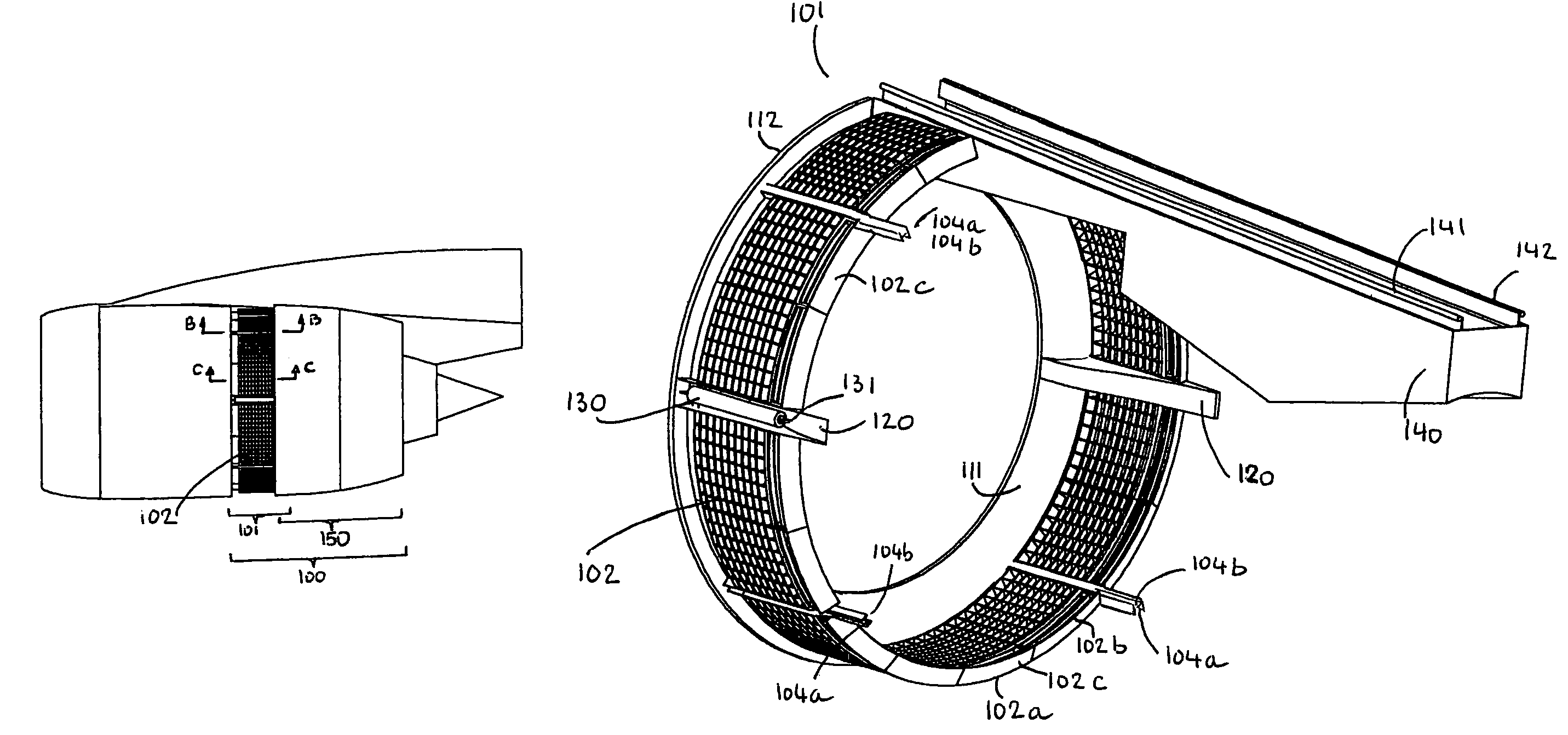
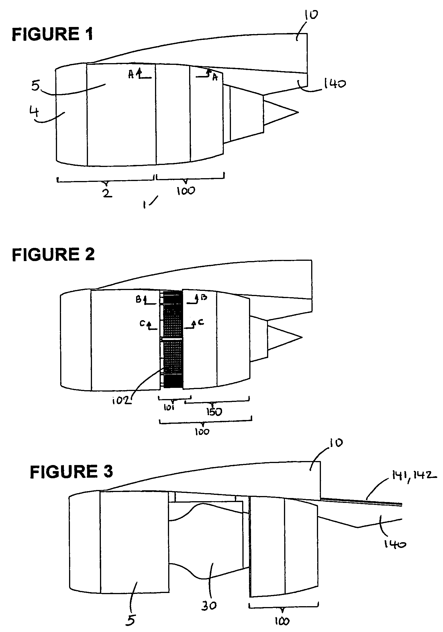
[0032]With reference to FIG. 1 the turbofan engine is housed by a nacelle 1 and is supported by a pylon 10 mounted on an aircraft. The nacelle 1 includes a forward portion 2 and a rear portion 100. The forward portion typically forms the air inlet 4 and the fan cowling 5. The rear portion 100 houses the thrust reverser and is composed of a translating cowl defined by a forward structure 101 and a rear structure 150 (FIG. 2). As it will be described, the forward and the rear structures have an operative mode that corresponds to the direct or reverse thrust modes of operation of the engine and an inoperative mode that corresponds to the access to the engine. FIG. 1 shows the operative mode of the translating cowl in its forward thrust position. FIG. 2 shows the operative mode...


PUM


Abstract

A translating cowl composed of two sub-structures forms the thrust reverser for a turbofan engine. The two sub-structures form the rear part of a nacelle, are translatable, and have operative and inoperative modes of operation. The operative mode is used for direct or reverse thrust operation of the engine and the inoperative mode is used for access to the engine.

Description

CROSS-REFERENCE TO RELATED APPLICATION[0001]The present application claims priority to U.S. Provisional Patent Application Ser. No. 60 / 702,683.FIELD OF INVENTION[0002]The present invention relates in general to aircraft engines, and in particular, to a fan thrust reverser for aircraft gas turbine engines.BACKGROUND OF INVENTION[0003]Turbofan engines are well known. They are typically composed of a fan driven at the front of the engine that draws air rearwardly through a by-pass duct that is defined by the core engine cowling and by the fan cowling spaced outwardly from the core cowling. In the case of a short nacelle, i.e., a separate flows nacelle, the generally annular duct that is bounded by the inner core cowling and the outer fan cowling, channels the by pass flow only while the core flow is channeled by the core nozzle inwardly installed to the core cowling. In the case of a long nacelle, i.e., a confluent flows nacelle, the upstream portion of said annular duct channels the b...

Claims


Application Information

Patent Timeline
Patent Type & Authority Patents(United States)
IPC IPC(8): F02K3/02
CPCF02K1/72Y02T50/671Y02T50/60
Inventor LAIR, JEAN-PIERRE
Owner AERONAUTICAL CONCEPT OF EXHAUST
Why Eureka
Try Eureka