
Shaping method and structure of woven fabric with a groove

a technology of woven fabric and shaping method, which is applied in the direction of weaving, open work fabrics, textiles and papermaking, etc., can solve the problems of increasing costs, reducing process efficiency, and increasing costs, and achieving the effects of reducing process efficiency, increasing costs, and reducing tension

Inactive Publication Date: 2009-02-03
CHING SHI IND
View PDF25 Cites 100 Cited by
  • Summary
  • Abstract
  • Description
  • Claims
  • Application Information

AI Technical Summary

Benefits of technology

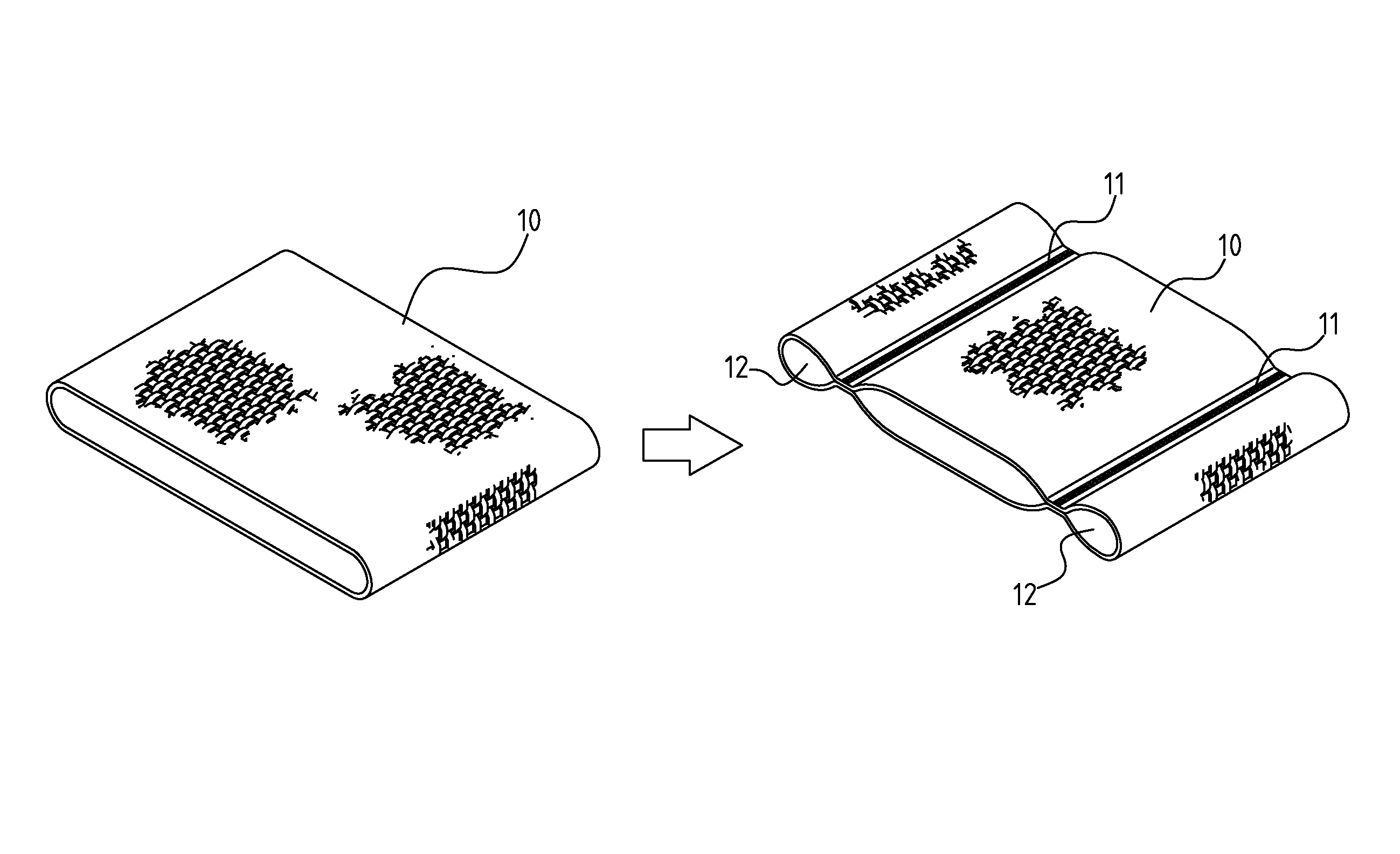
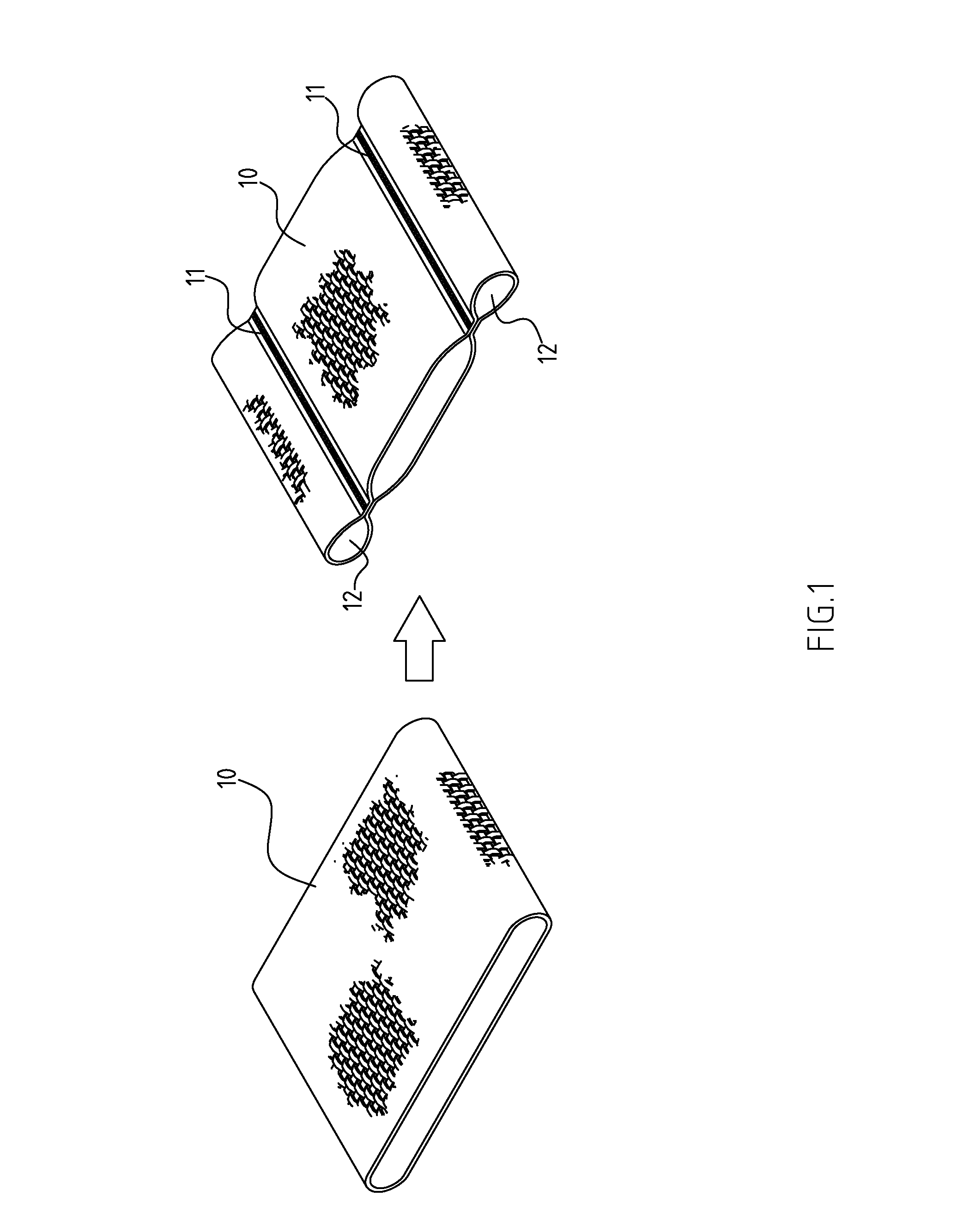
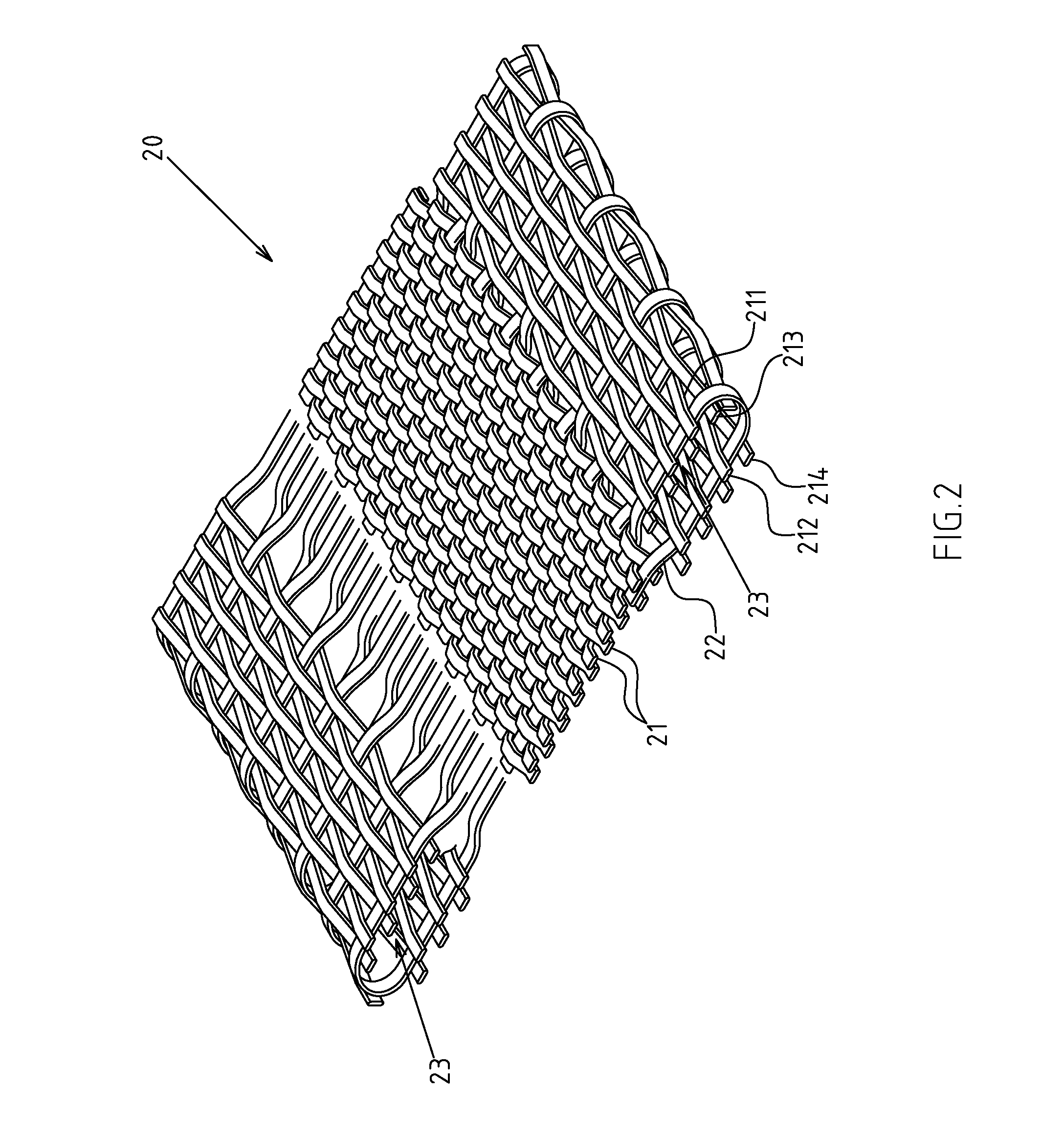
[0013]The improvements of the present invention are compared with the prior art. In the prior art, at the two sides of the edges of the circle tube fabric, stitching is needed to make close line to form the required groove, which reduces process efficiency and increases costs. And the tension is not good, either. In the present invention, a finished product of woven fabric 20 with groove 23 is made through flat weaving. Therefore, a normal flat weaving machine with low costs can be used for manufacturing. Additionally, during weaving of warp and weft, groove 23 can be formed directly without a second stitching process, such as stitching close used by prior art. This invention uses one thread of weft in the whole weaving process to make the whole structure united, and tension and elasticity are greatly increased. Therefore, the present invention can really reduce producing costs, and increase efficiency of production, structural tension and industrial use efficiency. It is practical and advanced.

Problems solved by technology

In the prior art, at the two sides of the edges of the circle tube fabric, stitching is needed to make close line to form the required groove, which reduces process efficiency and increases costs.
And the tension is not good, either.

Method used


Image

  • Shaping method and structure of woven fabric with a groove
  • Shaping method and structure of woven fabric with a groove
  • Shaping method and structure of woven fabric with a groove

Examples


Embodiment Construction

[0019]The features and the advantages of the present invention will be more readily understood upon a thoughtful deliberation of the following detailed description of a preferred embodiment of the present invention with reference to the accompanying drawings.

[0020]FIGS. 2 and 3 are the well implemented examples of the present invention of the shaping method and structure of woven fabric with a groove. The examples are only for illustration. The application for patent is not limited to the structure shown. Fabric 20 is made with warp 21 and weft 22 through flat inter-weaving, and the two sides of fabric 20 form a hollow groove. The present invention includes the groove 23, formed by warp 21 and weft 22 of fabric 20 itself.

[0021]The shaping method includes:[0022]a. Before weaving of fabric 20 (see FIG. 4), top longitude 211 and 213 and bottom warp 212 and 214 are laid in the area of groove 23.[0023]b. During the process of weaving of fabric 20, weft 22 is crossed over the crisscrossed...


PUM

PropertyMeasurementUnit
Structureaaaaaaaaaa
Sizeaaaaaaaaaa

Abstract

A shaping method for a woven fabric having a hollow looped portion includes the steps of laying top longitudinals and bottom longitudinals in a pattern corresponding to a shape and size of the hollow looped portions, forming top warps and bottom warps in a generally planar pattern, flat weaving a weft through and between the top warps and the bottom warps such that the top warps reside above the weft and said bottom warps reside below the weft, passing the weft between the top longitudinals and the bottom longitudinals in the hollow looped portion such that the top longitudinals reside above the weft and the bottom longitudinals reside below the weft.

Description

CROSS-REFERENCE TO RELATED U.S. APPLICATIONS[0001]Not applicable.STATEMENT REGARDING FEDERALLY SPONSORED RESEARCH OR DEVELOPMENT[0002]Not applicable.NAMES OF PARTIES TO A JOINT RESEARCH AGREEMENT[0003]Not applicable.REFERENCE TO AN APPENDIX SUBMITTED ON COMPACT DISC[0004]Not applicable.BACKGROUND OF THE INVENTION[0005]1. Field of the Invention[0006]The present invention relates generally to a shaping method and structure of woven fabric, and more particularly to a creative shaping method and structure of woven fabric with a groove.[0007]2. Description of Related Art Including Information Disclosed Under 37 CFR 1.97 and 37 CFR 1.98[0008]Woven fabric is used in various ways in practice. It can be used by itself and also can be combined with other materials to get another product. For example, a groove can be formed along the two sides of a piece of woven fabric for a pole or frame to get through. This combination is often used for backs or seats of leisure chairs[0009]The present inve...

Claims


Application Information

Patent Timeline
IPC IPC(8): D03D3/02D03D11/02D03D3/00D03D3/04D03D9/00
CPCD03D3/02D03D11/02D03D15/0088D03D15/46
Inventor HUANG, CHIN-HUI
Owner CHING SHI IND
Learn More