
Eureka
For R&D, Eureka makes reading and utilizing patents & technical documents easy.
Eureka AIR
Designed for self-driven R&D workflows. Generate viable solutions, solve complex R&D challenges, empower your innovation with AI.

Eureka Materials
Designed for material experts only. Revolutionize your material R&D, from search, analyze, to developing new materials.

TechResearch
Generate reliable direction feasibility study reports for your R&D in just a few steps.

TechSeek
Discover and master advanced knowledge NOW. Basics, ideas, possibilities, all at once.

TechMind
As an expert in R&D Theories, TechMind can generates customized viable solutions instantly.

TechRisk
Analyze your overall solution with one click, know your potential R&D risks in advance.

TechMonitor
Get weekly tech updates, stay abreast of the latest tech innovations and key insights.
Method and device for removing water from a steam plant
a technology for steam plants and water removal, applied in liquid degasification, lighting and heating apparatus, separation processes, etc., can solve problems such as pollution of the environment, and achieve the effect of reducing the volume of water which has to be purified and reducing the accumulation of waste water
- Summary
- Abstract
- Description
- Claims
- Application Information
AI Technical Summary
Benefits of technology
Problems solved by technology
Method used
Image

Examples
first embodiment
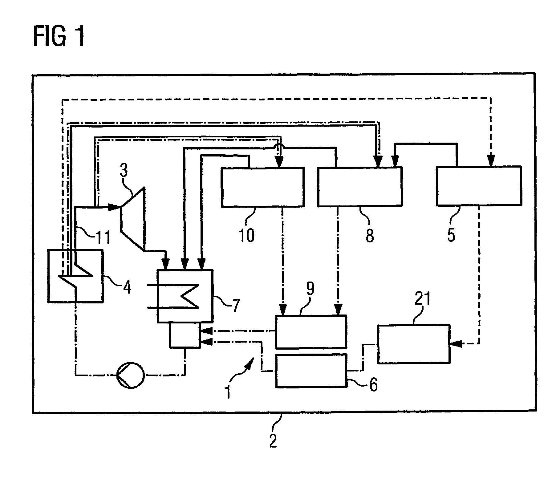
[0020]FIG. 1 shows a water removal device 1 according to the invention which forms part of a steam plant 2 for generating power. The water removal device 1 is sealed from the atmosphere to prevent the invasion of air into the water-steam circuit of the steam plant 2. The various components of the steam plant 2 illustrated in FIG. 1 are connected to each other by means of conduits for transferring water or steam. Broken connecting lines denote conduits for contaminated water, dot-dash connecting lines denote conduits for clean water, and solid connecting lines denote conduits for clean steam.
[0021]The steam plant 2 contains one or more steam turbines 3, the steam of which is supplied via a superheater. FIG. 1 shows a combination of superheater and evaporator with reference numeral 4. The water removal device 1 includes a tank which is configured as a separator tank 5 for the water-steam separation. An ingress of the separator tank 5 is connected via a conduit to an egress of the evap...
second embodiment
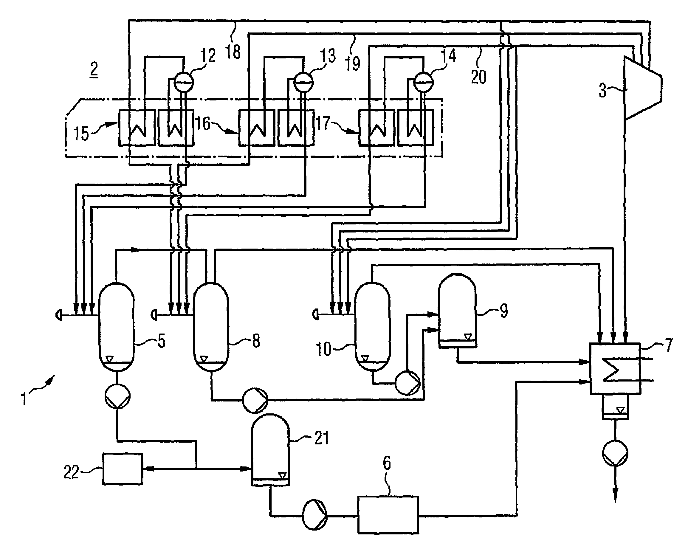
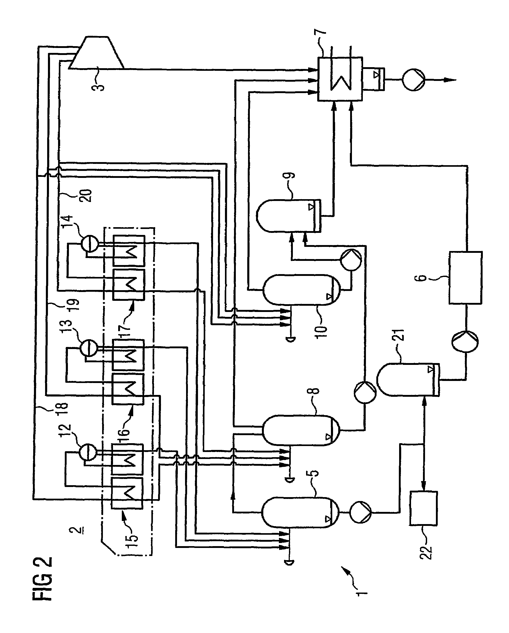
[0025]FIG. 2 shows the water removal device 1 according to the invention. The water removal device 1 forms part of the steam plant 2 which in this case comprises three steam drums with different pressure levels. The steam plant 2 contains a high-pressure (HP) steam drum 12 with a HP pressure level, a medium-pressure (MP) steam drum 13 with a MP pressure level, which is lower than the HP pressure level, and a low-pressure (LP) pressure drum 14 (sic) with a LP pressure level, which is lower than the MP pressure level. During operation steam is generated from water by the steam drums 12, 13 and 15 and associated evaporators. This steam is supplied via the steam drums 12, 13, 14 of the superheaters 15, 16, 17, associated with different pressure levels, and steam conduits 18, 19, 20 to the steam turbines 3 of the steam plant 2.
[0026]The three steam drums 12, 13, 14 are each connected to the separator tank 5 to introduce blown down, contaminated water therefrom. The separated, contaminate...
PUM
| Property | Measurement | Unit |
|---|---|---|
| volume | aaaaa | aaaaa |
| purity | aaaaa | aaaaa |
| volumes | aaaaa | aaaaa |
Abstract
Description
Claims
Application Information
 - R&D Engineer
- R&D Manager
- IP Professional
- Industry Leading Data Capabilities
- Powerful AI technology
- Patent DNA Extraction
Browse by: Latest US Patents, China's latest patents, Technical Efficacy Thesaurus, Application Domain, Technology Topic, Popular Technical Reports.
© 2024 PatSnap. All rights reserved.Legal|Privacy policy|Modern Slavery Act Transparency Statement|Sitemap|About US| Contact US: help@patsnap.com