Flange assembly

a technology of flanges and duct pieces, which is applied in the direction of fluid pressure sealing joints, sleeves/socket joints, mechanical equipment, etc., can solve the problems of time-consuming and laborious replacement of duct pieces in an existing exhaust system, and inability to meet the needs of continuous joining of two duct pieces

Active Publication Date: 2009-02-10
ATS PRODS
View PDF55 Cites 17 Cited by
  • Summary
  • Abstract
  • Description
  • Claims
  • Application Information

AI Technical Summary

Benefits of technology

[0049]Embodiments of the invention have number of advantages. For example, the flange assemblies according to embodiments of the invention may be easily connected or disconnected from other flange assemblies. For example, as described above, to connect two flange assemblies together, simple clamps, bolts, or the like may be used. To disconnect the two flange assemblies, the clamps, bolts, or the like may be removed and the flange assemblies can be separated. Unlike conventional duct joining methods and systems, one need to destroy a previously formed joint to remove a clogged piece of duct in an exhaust system. Also, embodiments of the invention are easy to use and fabricate, and also provide for a tight seal between adjacent duct sections. For instance, instead of conventional methods which include cutting duct pieces, forming a new seal with resin, and curing, embodiments of the invention can use a simple mechanical disconnect mechanism to remove a clogged duct piece.

Problems solved by technology

In some cases, the permanent joining of two duct pieces is undesirable.
These solids or semi-solids can clog up the duct pieces and shut down the exhaust system.
The conventional process of replacing duct pieces in an existing exhaust system is time consuming.
It is well known that a semiconductor fabrication facility is expensive to build.
The duct replacement / cleaning process mentioned above is also difficult for workers to perform and uses many steps.

Method used


Image

  • Flange assembly
  • Flange assembly
  • Flange assembly

Examples


Embodiment Construction

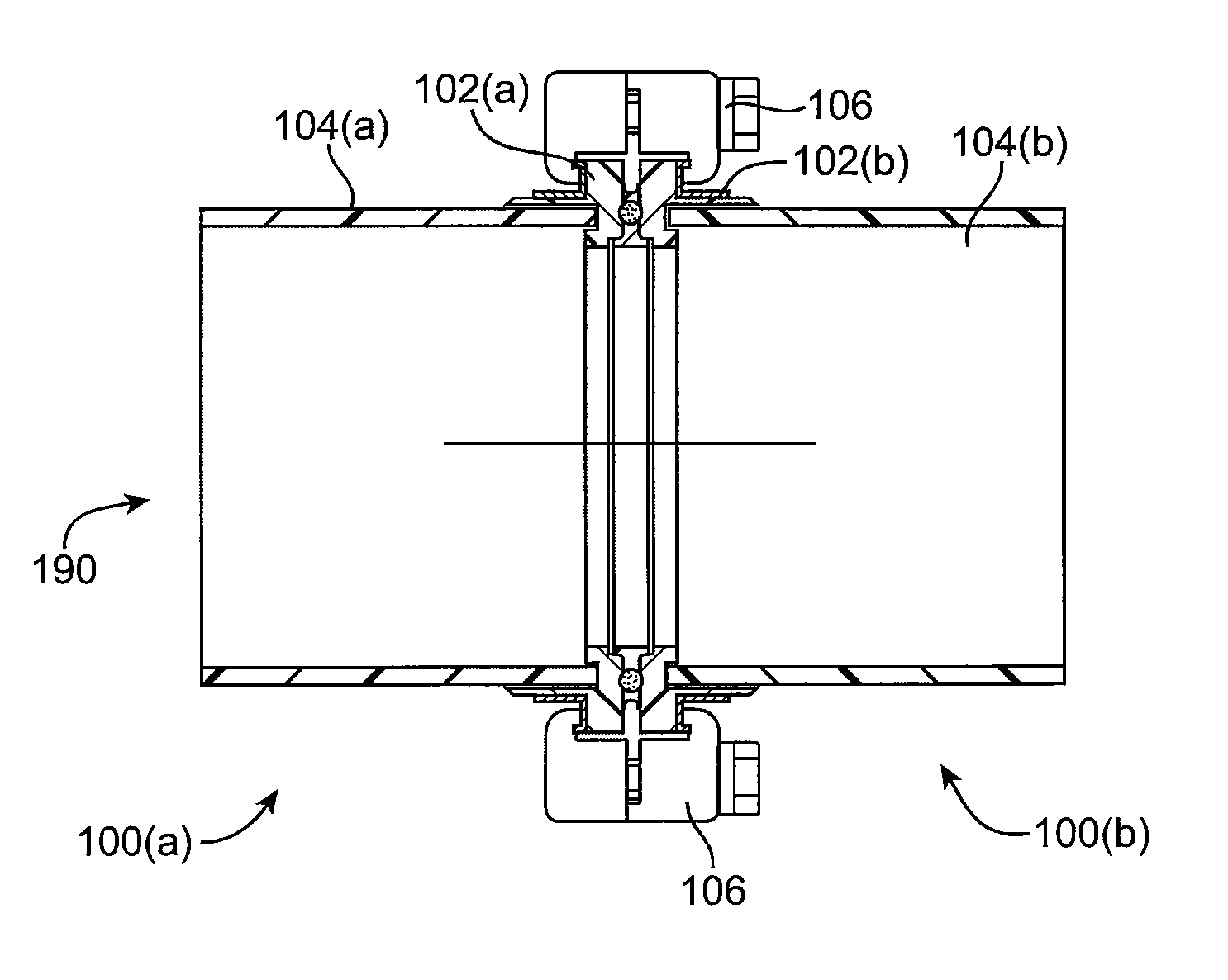
[0019]Embodiments of the invention are directed to directed to tubular systems, methods for making the tubular systems, and flange assemblies that can be used in the tubular systems. In one embodiment, the tubular system may be used in an exhaust system that uses air ducts. The air ducts and tubular systems according to embodiments of the invention are preferably adapted to transport liquids or gases containing corrosive materials.

[0020]Although air ducts and duct systems are described in detail in this application, it is understood that embodiments of the invention are not limited to air ducts and duct systems. For example, embodiments of the invention can also be used in piping systems that are used to transport liquids such as corrosive liquids.

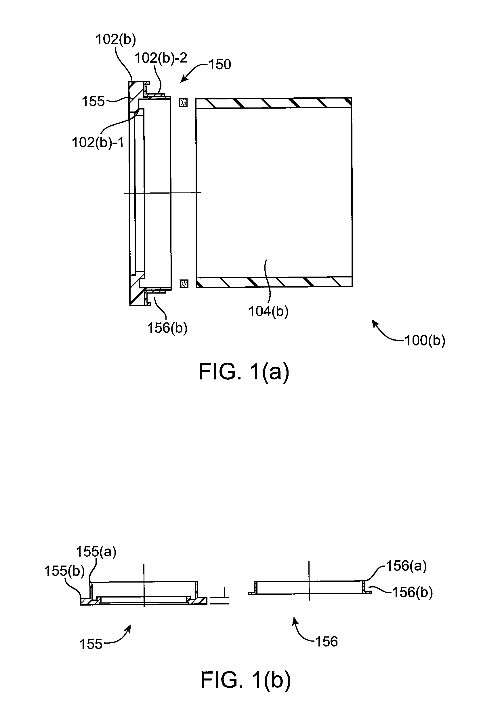
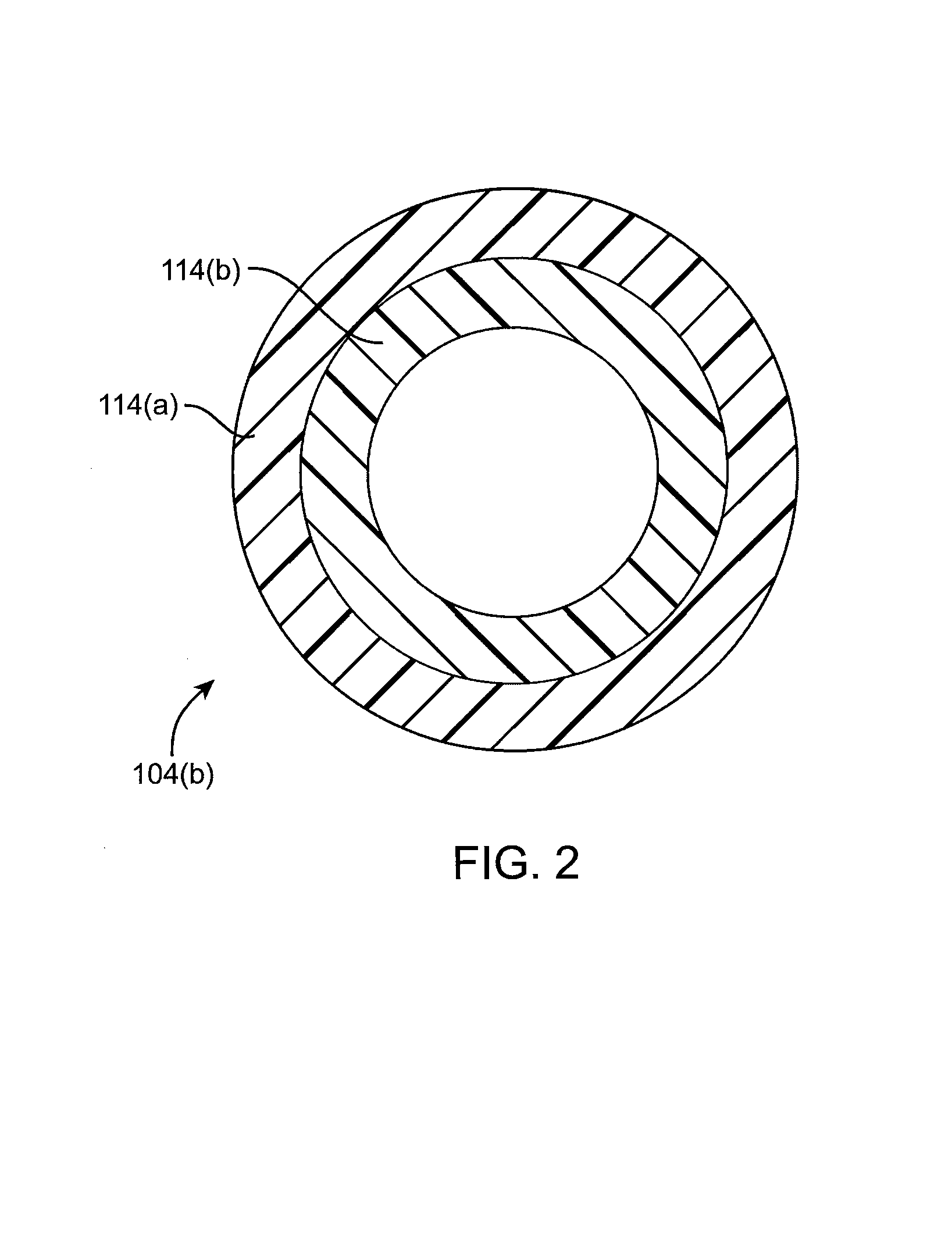
[0021]One specific embodiment is directed to a tubular system. The tubular system comprises a first flange assembly comprising (i) a first tubular structure comprising a passageway and comprising a fiber reinforced plastic material, (ii) a...


PUM

PropertyMeasurementUnit
corrosion resistantaaaaaaaaaa
fire resistantaaaaaaaaaa
shapeaaaaaaaaaa

Abstract

A flange assembly is disclosed. The assembly includes a tubular structure having a passageway and comprising a fiber reinforced plastic material, and a flange structure comprising an aperture coupled to the tubular structure using an attachment element.

Description

CROSS-REFERENCES TO RELATED APPLICATIONS[0001]This application is a non-provisional application of and claims priority to U.S. Provisional Application No. 60 / 670,931, filed on Apr. 12, 2005, which is herein incorporated by reference in its entirety for all purposes.BACKGROUND OF THE INVENTION[0002]One conventional method for joining fiber-reinforced plastic air ducts includes forming a seal around pieces of duct. The seal may be formed by wrapping a fiber-reinforced resin material around the abutting ends of the adjoining duct pieces and curing the same. This seal permanently joins the duct pieces.[0003]In some cases, the permanent joining of two duct pieces is undesirable. For example, in the semiconductor industry, process gases that are exhausted in the joined duct pieces may react and may form solids or semi-solids. These solids or semi-solids can clog up the duct pieces and shut down the exhaust system. To clean out the exhaust system, one needs to cut the joined duct pieces, a...

Claims


Application Information

Patent Timeline
Patent Type & Authority Patents(United States)
IPC IPC(8): F16L23/00F16L21/02
CPCF16L23/032F16L23/036F16L23/125F16L23/18Y10T403/18Y10T403/64Y10T403/3981F16B2200/50F16B2200/509
Inventor WELLMAN, RAYWILLIAMS, DOUG
Owner ATS PRODS
Why Eureka
Try Eureka