Method and an apparatus for determining the efficiency of dialysis

a dialysis efficiency and apparatus technology, applied in the field of dialysis clearance, can solve the problem of difficult to determine the specific benefit of the dialysis process, and achieve the effect of improving the result of the dialysis, prolonging treatment time, and low ratio

Active Publication Date: 2009-02-10
GAMBRO LUNDIA AB
View PDF10 Cites 57 Cited by
  • Summary
  • Abstract
  • Description
  • Claims
  • Application Information

AI Technical Summary

Benefits of technology

[0018]The object of the present invention is therefore to alleviate the problems above and thus accomplish an improved estimation of the whole body clearance of the dialyzer on a particular patient and enabling identification of cases where an improvement is necessary, and probably possible.
[0021]According to a preferred embodiment of this aspect of the invention, the whole body clearance ratio is determined by: measuring a final blood urea concentration, either immediately, or approximately one minute after the end of the treatment; measuring an equilibrated blood urea concentration no earlier than approximately one half hour to one hour after the end of the treatment; and dividing said final blood urea concentration by said equilibrated blood urea concentration. Thereby, a reliable measure is found, which reflects the process efficiency with respect to the patient.
[0031]A general advantage attained by the invention is that, based on the whole body clearance ratio for a dialysis treatment of a particular patient, a following treatment of the same patient can be made more efficient. Namely, if a relatively low ratio is determined, the next time, certain actions can be taken to improve the result of the dialysis. For instance, the treatment time can be prolonged, the composition of the dialysate can be altered, or some kind of intervention procedure with respect to the patient may be performed. The intervention procedure may involve subjecting the patient to physical exercise, massage, a change in the ambient temperature, an increased fluid intake, acupuncture, and / or medication affecting the systemic blood flow or the blood flow distribution in the patient's body.

Problems solved by technology

Since each patient has his / her own characteristic response to a particular treatment, it is otherwise very difficult to determine the specific benefit of the dialysis process.

Method used


Image

  • Method and an apparatus for determining the efficiency of dialysis
  • Method and an apparatus for determining the efficiency of dialysis
  • Method and an apparatus for determining the efficiency of dialysis

Examples


Embodiment Construction

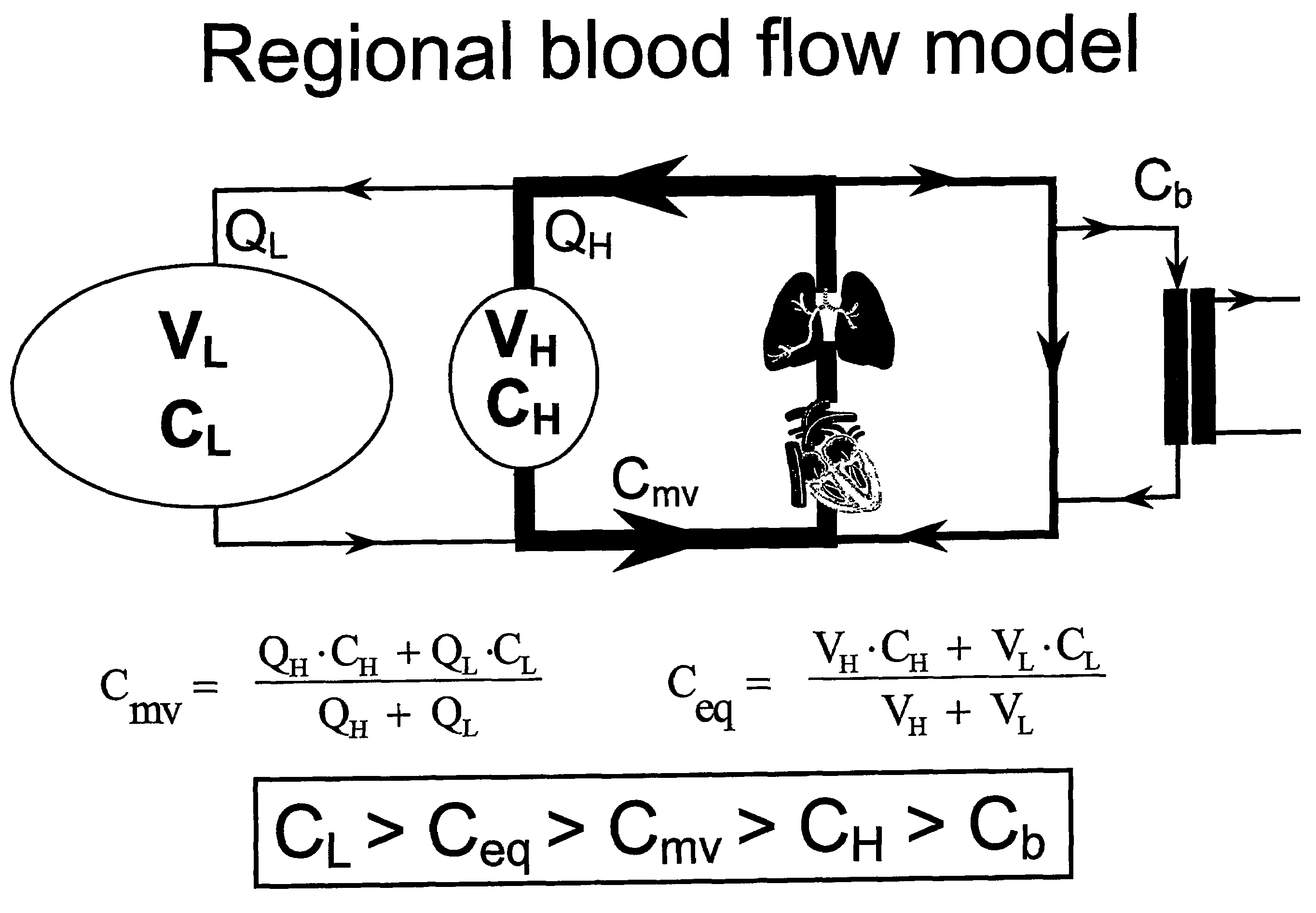
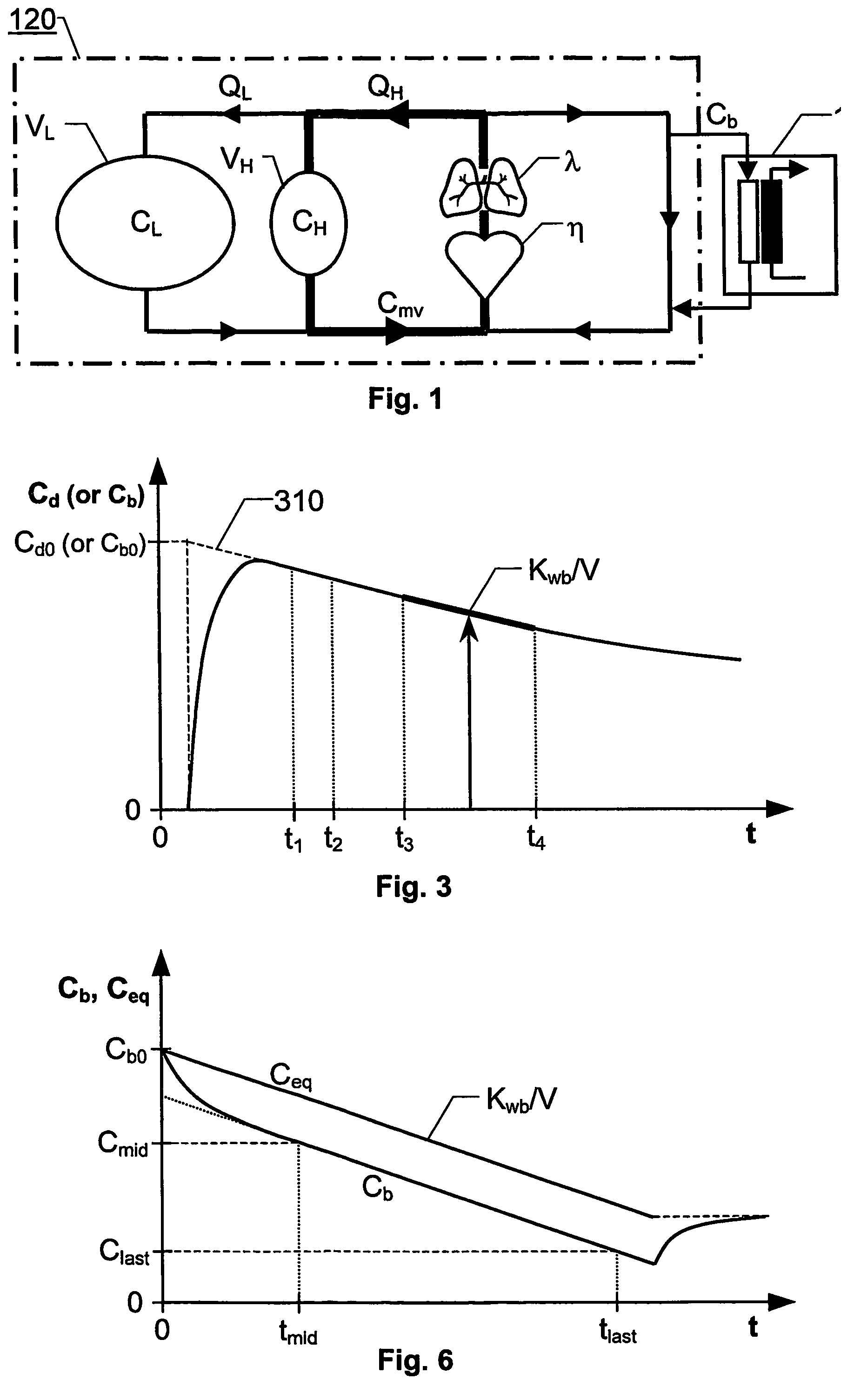
[0040]Returning now to the FIG. 1, in contrast to Daugirdas and Schneditz, the invention presumes that the pool volumes VL and VH are constant. Thus, no ultrafiltration is presumed to take place, and the generation of urea is neglected. This means that it is possible to set up one differential equation for the ratio between the two pool concentrations CL and CH. Moreover, it can be shown that the ratio between the two pool concentrations CL and CH tends towards a constant. This in turn, means that the clearance ratio: “whole body clearance”-to-“effective clearance” Kwb / Keff (which equals the ratio: “mixed venous concentration”-to-“equilibrated concentration” Cmv / Ceq) also tends towards a constant. The factors which determine the steady state ratios are the fraction of the large pool volume VL to the entire blood volume V=VL+VH, the fraction of the blood flow QL in the large pool to the total systemic blood flow Q, and the fraction of the effective clearance Keff to the total systemi...


PUM

PropertyMeasurementUnit
timeaaaaaaaaaa
concentrationaaaaaaaaaa
flow rateaaaaaaaaaa

Abstract

The invention relates to characterization of a dialyzer's capacity to accomplish a dialysis clearance of a patient, and strategies for improving the efficiency of a dialysis treatment of the patient The invention involves determining a whole body clearance ratio (420) for a dialysis treatment of a patient (410). The whole body clearance ratio expresses how well the patient responds to a potential cleaning capacity of a dialyzer, which is used to perform the treatment.

Description

CROSS REFERENCE TO RELATED APPLICATION[0001]This application is an national phase application based on PCT / SE2003 / 001666, filed Oct. 28, 2003, which claims the benefit of U.S. Provisional Application No. 60 / 422,410, filed Oct. 30, 2002, the content of both of which is incorporated herein by reference in its entirety.THE BACKGROUND OF THE INVENTION AND PRIOR ART[0002]The present invention relates generally to dialysis clearance. More particularly the invention relates to a method of estimating a process efficiency of a dialysis system according to the preamble of claim 1, a method of estimating a whole body clearance ratio according to the preamble of claim 6, corresponding computer programs and computer readable media according to claims 11 and 13 respective 12 and 14, an apparatus adapted to estimate a whole body clearance ratio according to claim 16, as well as use of this apparatus according to claim 17. The invention also relates to a method of performing a dialysis treatment pr...

Claims


Application Information

Patent Timeline
Patent Type & Authority Patents(United States)
IPC IPC(8): A61M1/36A61M37/00C02F1/44A61M1/14A61M1/16A61M1/34
CPCA61B5/14546A61M1/14A61M1/16A61M1/1609A61M1/1613A61M1/1617A61M1/3406A61M2205/33A61M2205/50A61M1/341A61M2202/0498A61M2205/15A61M1/3609
Inventor STERNBY, JAN PETER
Owner GAMBRO LUNDIA AB
Why Eureka
Try Eureka