High-pressure discharge lamp

a discharge lamp and high-pressure technology, applied in the direction of discharge lamp, electric discharge lamp, discharge tube luminescnet screen, etc., can solve the problems of considerable reduction in the useful devitrification of the cylindrical envelope in the central region, etc., to reduce the diameter of the cylindrical envelope, and prolong the service life of the lamp.

Inactive Publication Date: 2009-02-10
HERAEUS NOBLELIGHT LTD
View PDF14 Cites 0 Cited by
  • Summary
  • Abstract
  • Description
  • Claims
  • Application Information

AI Technical Summary

Benefits of technology

[0004]For that reason, the present invention aims at providing a lamp whose service life is prolonged when it is operated in the flashing mode. According to the present invention, any signs of devitrification have been shown to become substantially less, if the two end regions of the pressure chamber are designed differently at least outside of the discharge chamber. The discharge chamber is defined as the space between the anode and the cathode. The pressure chamber is defined as the entire space inside the cylindrical envelope. As a result, the high-pressure discharge lamp according to the invention comprises an asymmetry in the pressure chamber outside of the discharge chamber in the end regions of the pressure chamber. It is assumed that the spatial asymmetry causes the development of asymmetric flow conditions which will then contribute to prolonging the service life of the lamp. The devitrification in the central region of the cylindrical envelope, preferably formed as a tube closed on both ends, is strongly reduced, in particular with flash lamps.
[0005]The cylindrical envelope is preferably made of quartz glass. It is advantageous if at least one of the electrodes is, at least substantially, designed in the form of a cylinder. It is beneficial to have a flow resistance that is lower in the end region comprising the anode than in the end region comprising the cathode (i.e., the flow cross-section at the cathode is smaller than at the anode). The radial spacing between the electrode and the cylindrical envelope may be at least approximately 200 μm greater at the anode than at the cathode.
[0006]It has also been shown to be advantageous if the anode comprises a through opening ending in the discharge chamber, wherein a bore preferably not running parallel, but preferably running perpendicular to the longitudinal axis, is connected to an axial bore.
[0008]The diameter of the cylindrical envelope can, advantageously, be reduced at least in the region of one electrode, preferably the cathode, such that radial spacing from the electrode is reduced. As a result, the flow resistance at the cathode can be increased as compared with the flow resistance at the region of the anode. Appropriately, the diameter is not reduced along the complete longitudinal extension of the electrode, but preferably at its circumferential region toward the discharge chamber. Preferably, the cold fill pressure of the filling gas of the lamp is in the range of about 1.5-3 bar.

Problems solved by technology

The use of high-pressure discharge lamps as flash lamps often gives rise to the problem that, in the course of lamp operation, the cylindrical envelope is devitrified approximately in its central region.
As a result, the useful life of the lamp decreases to a considerable degree.

Method used


Image

  • High-pressure discharge lamp
  • High-pressure discharge lamp

Examples


Embodiment Construction

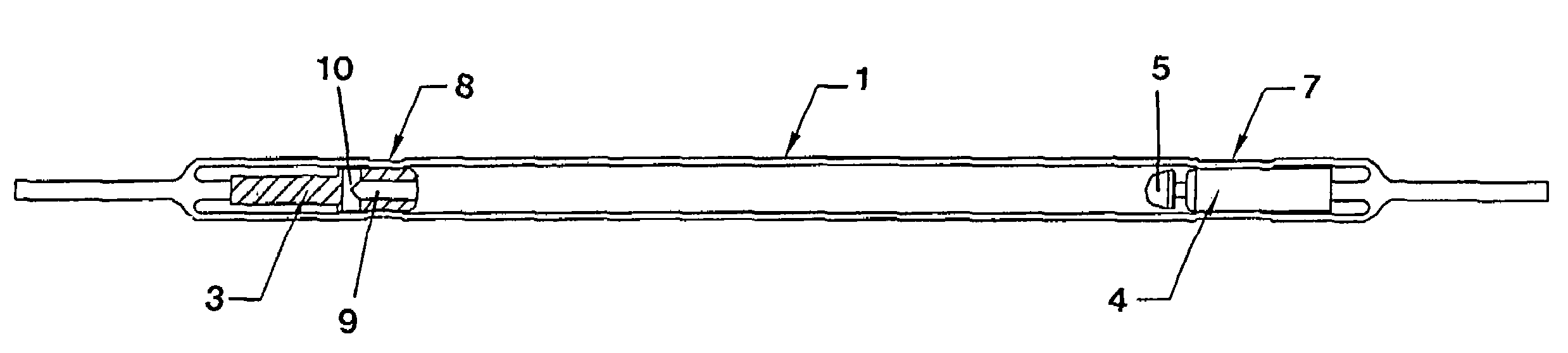
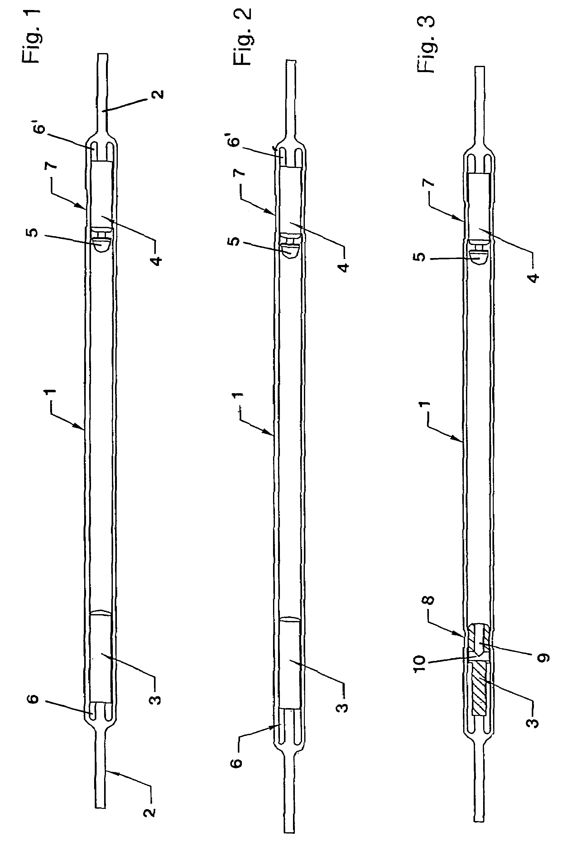
[0013]FIG. 1 shows a high-pressure discharge lamp used as a flash lamp and comprising a cylindrical envelope 1 made of a quartz tube. The quartz tube is closed at both of its ends. A tungsten filament, which is provided as connection electrode 2, is passed through each of the closed ends. The connection electrode 2 is fused in the quartz glass.

[0014]One connection electrode 2 each runs respectively to the anode 3 and the cathode 4. Anode 3 and cathode 4 are substantially cylindrical in shape. The discharge chamber is provided between the anode 3 and the cathode 4. At its end facing the discharge chamber, the cathode comprises an electrode head 5 that is axially connected to the cylindrical cathode body. A cavity 6, 6′ is provided between the lead-through of the lead electrodes 2 and the cylindrical bodies of the anode 3 and the cathode 4. In the embodiment according to FIG. 1, the two cavities 6, 6′ are approximately equal in size, whereas in the embodiment according to FIG. 2, the ...


PUM


Abstract

A high-pressure discharge lamp has a pressure chamber with two opposite end regions and delimited by a cylindrical envelope made of glass. An electrode is provided at each of the two end regions, the electrodes projecting into the pressure chamber and being arranged in the pressure chamber as anode and cathode. A discharge chamber is formed between the electrodes. The two end regions of the pressure chamber are designed differently at least outside of the discharge chamber.

Description

BACKGROUND OF THE INVENTION[0001]The present invention relates to a high-pressure discharge lamp having a pressure chamber with two opposite ends and delimited by a cylindrical envelope made of glass. An electrode is provided at each of the ends, the electrodes projecting into the pressure chamber and being arranged in the pressure chamber as anode and cathode, such that a discharge chamber is formed between the electrodes. The invention relates, in particular, to a high-pressure discharge lamp that is used as a flash lamp.[0002]High-pressure discharge lamps have already been disclosed in great variety, for example in European Patent EP 374 679 B 1 or in European published patent application EP 1 227 510 A1. Similar discharge lamps have, for example, also been disclosed in U.S. Pat. No. 5,979,187.[0003]The use of high-pressure discharge lamps as flash lamps often gives rise to the problem that, in the course of lamp operation, the cylindrical envelope is devitrified approximately in...

Claims


Application Information

Patent Timeline
Patent Type & Authority Patents(United States)
IPC IPC(8): H01J61/88H01J61/073H01J61/30H01J61/36H01J61/90
CPCH01J61/0732H01J61/30H01J61/366H01J61/90
Inventor KRONERT, UWEWOFFENDIN, JEREMYFLETCHER, MICHAEL
Owner HERAEUS NOBLELIGHT LTD
Why Eureka
Try Eureka