
High performance communication system

a communication system and high-performance technology, applied in the field of communication systems, can solve the problems of increasing power consumption, limiting the throughput of existing lwd tool strings with a single wire communication bus, and requiring large quantities of information

Inactive Publication Date: 2009-02-17
HALLIBURTON ENERGY SERVICES INC
View PDF18 Cites 25 Cited by
  • Summary
  • Abstract
  • Description
  • Claims
  • Application Information

AI Technical Summary

Problems solved by technology

Petroleum drilling and production operations require large quantities of information relating to parameters and conditions downhole.
Due to power and technology limitations, existing LWD tool strings with a single wire communication bus have limited throughput.
However, such techniques increase power consumption, are not compatible with existing tool assemblies, and require substantial redesign and modification of these assemblies.

Method used


Image

  • High performance communication system
  • High performance communication system
  • High performance communication system

Examples


Embodiment Construction

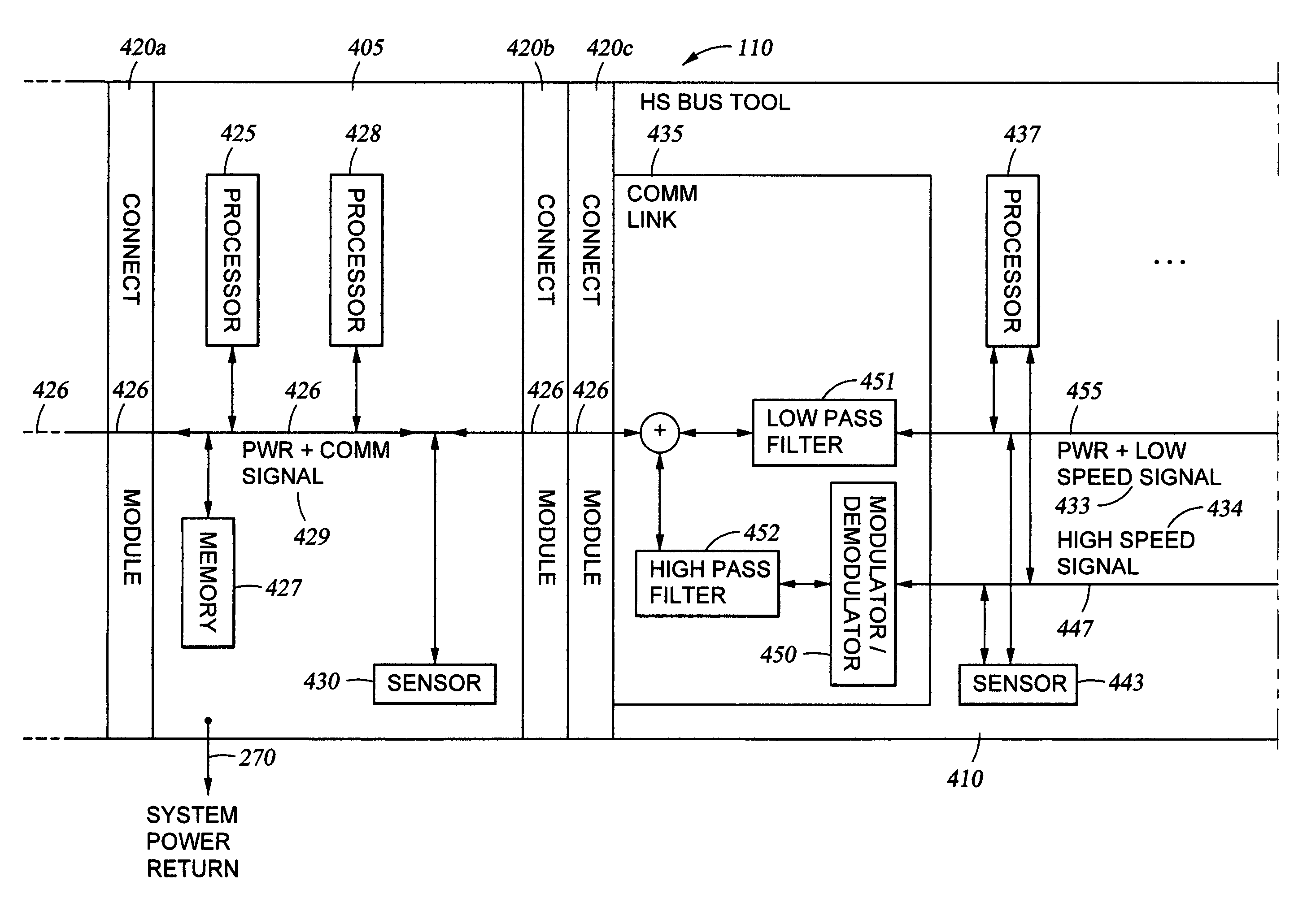
[0019]A high performance communication system is described that allows tool assemblies to transfer large quantities of data to each other at high speeds. A single wire cable running the length of the tool string has two communication channels at different frequencies. A low speed communication channel includes a low speed signal over one band of frequencies. A high speed communication channel contains a high speed signal over a different band of frequencies.

[0020]In some embodiments of the invention, the high speed communication channel is added on top of the existing low speed communication channel in tool assemblies present in the tool string. Adding two communication channels on a single wire communication bus running the length of the tool string allows the use of existing tool joints to connect the tool assemblies. Thus, a plurality of first tool assemblies capable of using only the low speed communication channel may operate and function together with a plurality of second too...


PUM


Abstract

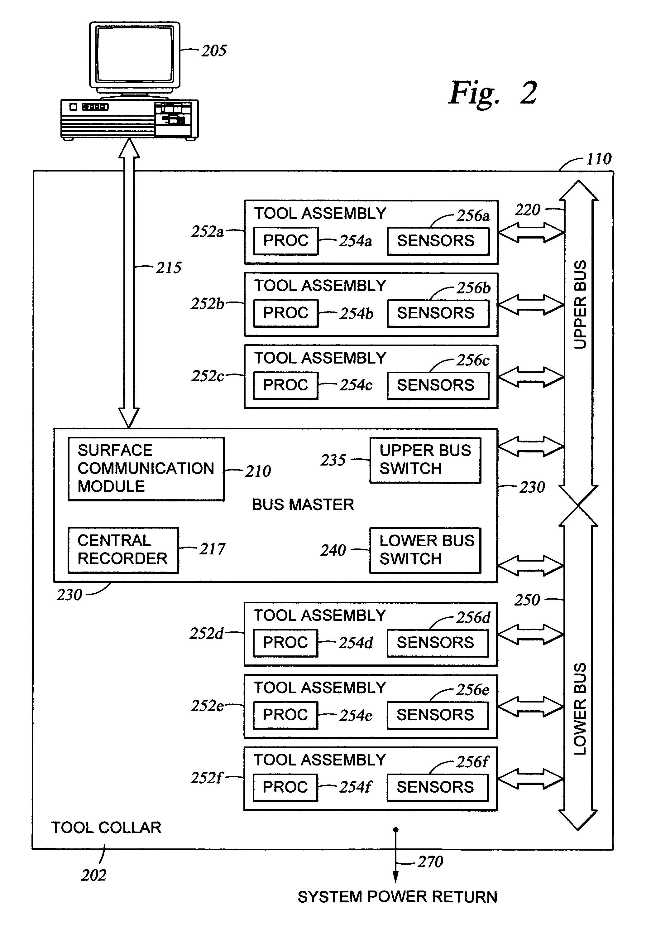
A system for communicating information in a borehole between tool assemblies in a tool string includes receiving an information signal and separating a first signal that may be a power and low speed signal. A second signal is separated and demodulated from the information signal. The first signal and second signal are transmit to electronic devices that process data from an earth formation. After the first and second signals are transmit to one or more electronic devices, the signals are modulated and / or filtered and then combined into the information signal. The first signal is at one frequency and the second signal is at a different frequency. The apparatus includes a main signal line that couples to a second signal line and third signal line in the tool assembly.

Description

TECHNICAL FIELD OF THE INVENTION[0001]The present invention relates to a communication system capable of operating in difficult environmental conditions. More particularly, the present invention relates to a high bandwidth and high speed communication system that allows tool assemblies in a borehole tool string to communicate with each other and transfer large amounts of information.BACKGROUND OF THE INFORMATION[0002]Petroleum drilling and production operations require large quantities of information relating to parameters and conditions downhole. Such information typically includes characteristics of the earth formations traversed by the borehole, along with data relating to the size and configuration of the borehole itself. The collection of information relating to conditions downhole, which commonly is referred to as “logging,” may be performed by several techniques that may require the transmission of large quantities of information through the borehole.[0003]In conventional oil...

Claims


Application Information

Patent Timeline
Patent Type & Authority Patents(United States)
IPC IPC(8): G01V3/00
CPCG01V11/002
Inventor MORYS, MARIAN
Owner HALLIBURTON ENERGY SERVICES INC
Learn More