Premix burner

a burner and pre-mix technology, applied in the direction of burners, combustion types, combustion processes, etc., can solve the problems of high nox emissions, backflash occurrence, and increase the risk of so-called vortex chamber backlash, so as to reduce the flow velocity, reduce the risk of backlash being significantly reduced, and increase the pre-mix burner's swallowing capacity.

Inactive Publication Date: 2009-02-17
ANSALDO ENERGIA IP UK LTD
View PDF6 Cites 10 Cited by
  • Summary
  • Abstract
  • Description
  • Claims
  • Application Information

AI Technical Summary

Benefits of technology

[0013]One of numerous aspects of the present invention includes developing a premix burner for a heat generator, especially for firing a combustion chamber to drive a gas turbine plant, with partial cone shells which make up a vortex generator, and which encompass a conically widening vortex chamber and mutually define tangential air inlet slots, and also with feeds for gaseous and / or liquid fuel, of which at least one is arranged along the air inlet slots on the partial cone shells, and at least one other is arranged along a burner axis which centrally passes through the vortex chamber, in such a way that even in larger dimensioned gas turbine plants which require a larger burner load, its use becomes possible without the constructional design of the premix burner having to be significantly altered.
[0014]Despite the measures which maximize the burner capacity, it is especially necessary to keep the pollutant emission which is produced by the burner as low as possible. A further desirable aspect concerns the overall size of such a premix burner which is to be kept as compact and small as possible. Naturally, it is necessary, moreover, to always ensure the operational safety of a premix burner which is modified according to the invention, and, despite the measures which increase the burner capacity, to minimize (as much as completely excluding) the increasing risk regarding backflash occurrences in high-capacity burner systems.
[0016]Another aspect of the present invention is based on the concept of increasing the swallowing capacity of an as known per se premix burner which is adapted in an optimized manner to a corresponding burner capacity, without at the same time altering the geometry dimensions which determine the overall size of the premix burner, like length and diameter of the premix burner.
[0018]By the increase in the number n of air inlet slots which are defined in each case by a corresponding number n of partial cone shells, the compact burner design can be basically maintained in an unaltered way and, at the same time, circumvents the problem of an increased fuel distribution through the central liquid fuel injection in the center of the burner, especially as the velocity of the air flows which flow through the premix burner increases in the same measure, by which the air throughput, and therefore the swallowing capacity of the premix burner, is also increased. This is also the reason for the risk of a backflash being able to be significantly reduced despite larger burner capacities. On the other hand, however, an increase of the so-called burner nominal velocity leads to the formation of a spatially stable backflow zone downstream of the burner and the flame stabilization, which is associated with it, being affected. In order to accordingly take into account the flame stabilization, it is necessary to correspondingly reduce the flow velocity of the fuel-air mixture which is formed and which issues from the premix burner. In the case of a premix burner, in which a mixer tube is connected downstream of the vortex generator, the inner contour of the mixer tube is formed in the flow direction as a diffuser, i.e., in a preferred embodiment the inner contour of the mixer tube is widened by a suitably predetermined cone angle α relative to the flow axis.
[0019]In the case of a premix burner without a mixer tube which is connected downstream, an increase of the number of air slots leads to a shift of the backflow bubble to the burner outlet. As a result, the premixing is also improved and lower emission values also ensue.

Problems solved by technology

The vortex flow, however, on account of the increasing vortex in the flow direction inside the vortex chamber, becomes unstable and changes into an annular vortex flow with a backflow zone in the flow core.
In this way, with a typical feed of liquid fuel along the burner axis, a rich fuel-air mixture, which is formed along the burner axis, becomes apparent at the location of the cone apex of the conically widening vortex chamber, especially in premix burners of larger design, as a result of which the risk of the so-called backflash in the region of the vortex chamber increases.
Such backflashes lead on the one hand inevitably to high NOx emissions, particularly through which fuel-air mixture portions which are not completely mixed through are combusted.
On the other hand, backflash occurrences are hazardous especially because of this and are to be avoided since they can lead to thermal and also mechanical stresses and, as a consequence of this, can lead to irreversible damage to the structure of the premix burner.
This incurs high costs which it is necessary to avoid.
It is clear, moreover, that single-row burner arrangements, but especially double-row or multi-row burner arrangements, around in each case one combustion chamber, demand large constructional volumes.
On the other hand, however, an increase of the so-called burner nominal velocity leads to the formation of a spatially stable backflow zone downstream of the burner and the flame stabilization, which is associated with it, being affected.

Method used


Image

  • Premix burner
  • Premix burner
  • Premix burner

Examples


Embodiment Construction

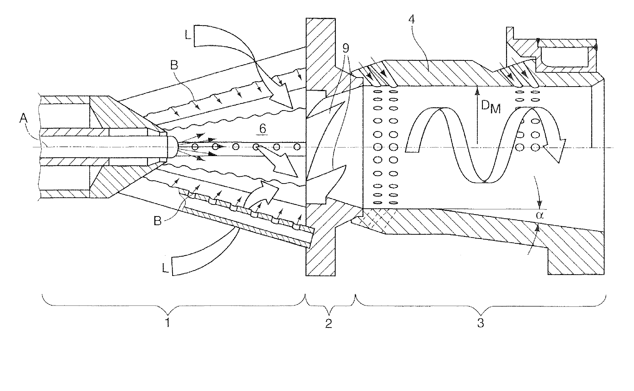
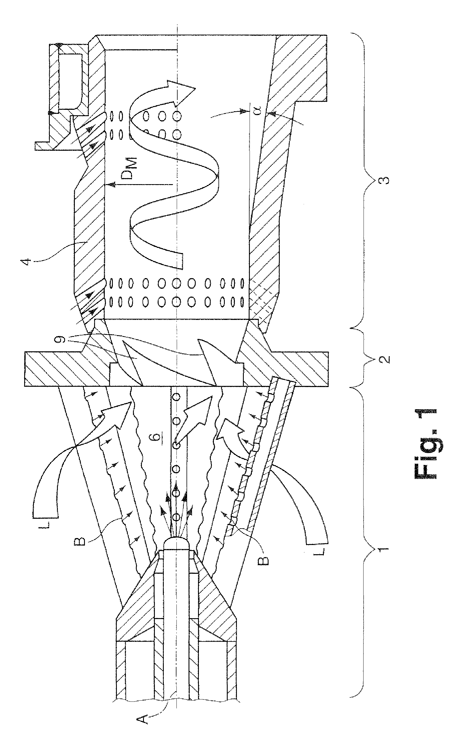
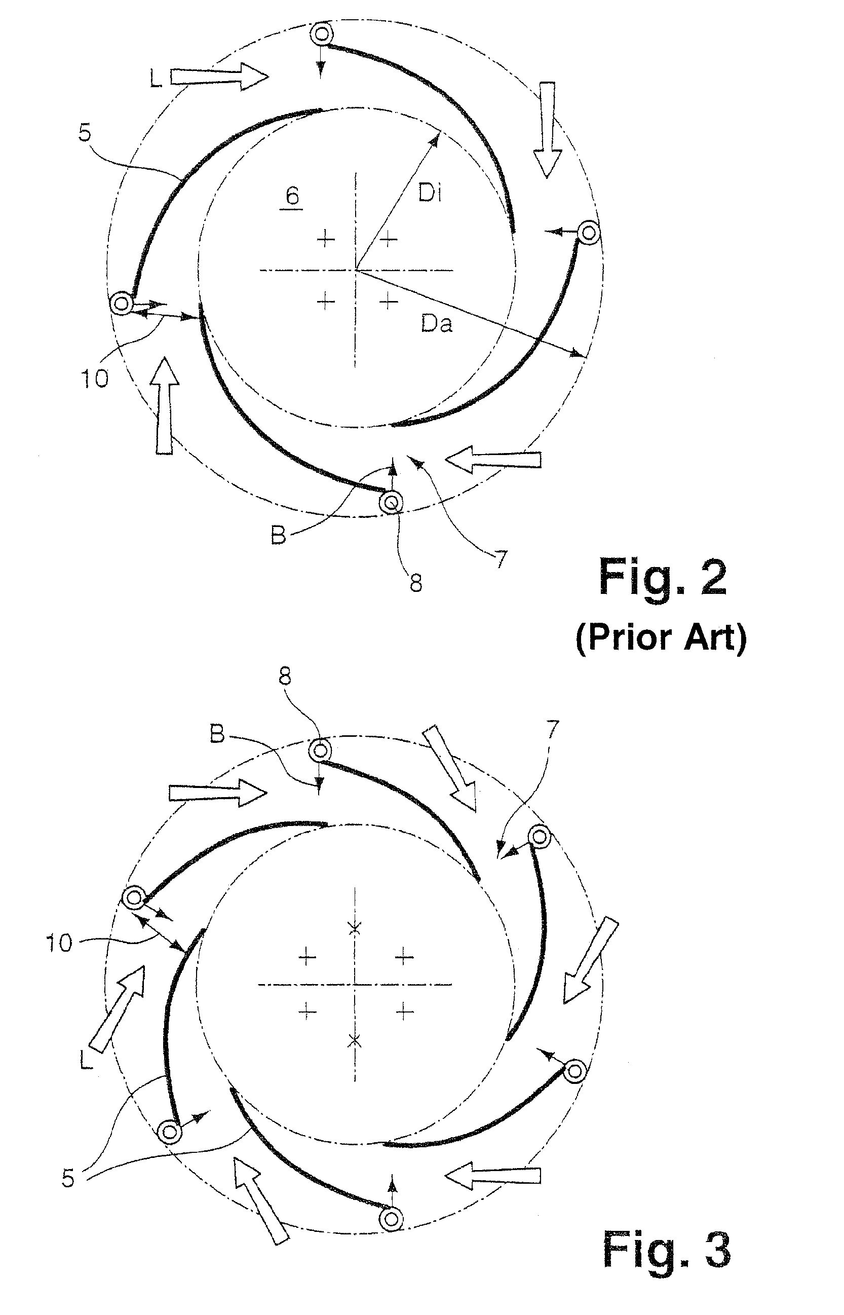
[0024]In FIG. 1, a longitudinal sectional view through a burner arrangement is shown, which burner arrangement basically has three sub-components: a conically formed premix burner 1, a transition piece 2, and also a mixing path 3 which is formed in the form of a tubular mixing element 4. The upper half of the longitudinal sectional view according to FIG. 1 represents an as known per se premix burner arrangement, with a vortex generator 1, the vortex chamber of which is encompassed by n=4 partial cone shells 5 which altogether define n=4 air inlet slots 7. A cross-sectional view of such a known vortex generator 1 is shown in FIG. 2. The four partial cone shells 5, which encompass an inner vortex chamber 6, are clearly apparent from this view. The four air inlet slots 7 define an outside premix burner diameter Da, and also an inside diameter Di which defines the size of the vortex chamber 6. In addition, the respective mutual spatial offset of the partial cone shells with regard to th...


PUM


Abstract

A premix burner for a heat generator has partial cone shells (5) which make up a vortex generator, and which encompass a conically widening vortex chamber (6) and mutually define tangential air inlet slots (7), and also with feeds for gaseous and / or liquid fuel, of which at least one is arranged along the air inlet slots (7) on the partial cone shells (5), and at least one other is arranged along a burner axis (A) which centrally passes through the vortex chamber (6). At least n partial cone shells (5) encompass the vortex chamber (6), and define n air inlet slots (7), with n≧3, preferably n≧5, the n air inlet slots (7) each have at least a maximum slot width (10) which is equal to or larger than that slot width (10) which a generic type premix burner (1) of the same size and dimensioning with m≦2 partial cone shells (5) and m air inlet slots (7) has.

Description

[0001]This application is a Continuation of, and claims priority under 35 U.S.C. § 120 to, International application number PCT / EP2005 / 055612, filed 27 Oct. 2005, and claims priority therethrough under 35 U.S.C. §119 to Swiss application number 01814 / 04, filed 3 Nov. 2004, the entireties of which are incorporated by reference herein.BACKGROUND[0002]1. Field of Endeavor[0003]The invention relates to a premix burner for a heat generator, with partial cone shells which make up a vortex generator, and which encompass a conically widening vortex chamber and mutually define tangential air inlet slots, and also with feeds for gaseous and / or liquid fuel, of which at least one is arranged along the air inlet slots on the partial cone shells, and at least one other is arranged along a burner axis which centrally passes through the vortex chamber.[0004]2. Brief Description of the Related Art[0005]Generic type premix burners have effectively been used for many years for firing combustion chambe...

Claims


Application Information

Patent Timeline
Patent Type & Authority Patents(United States)
IPC IPC(8): F23D14/62
CPCF23C7/002F23D14/02F23C2900/07002
Inventor KNOEPFEL, HANS PETER
Owner ANSALDO ENERGIA IP UK LTD
Why Eureka
Try Eureka