Instrument and method for guiding surgical implants and instruments during surgery

a surgical implant and surgical technology, applied in the field of surgical devices and methods, can solve the problems of difficulty in insertion of various implant components to the surgical site, need to be applied, and difficulty in assembly, delivery and manipulation of the implant components described hereinabov

Active Publication Date: 2009-02-17
WARSAW ORTHOPEDIC INC
View PDF74 Cites 221 Cited by
  • Summary
  • Abstract
  • Description
  • Claims
  • Application Information

AI Technical Summary

Benefits of technology

[0005]In one embodiment, a device is provided for guiding surgical implants to a bone anchor during surgery. The device includes a first bone anchor extender releasably attachable to a first portion of a head portion of the bone anchor. The first bone anchor extender includes a first clip for receiving and releasably attaching to the first portion of the head portion of the bone anchor, and a first extension portion extending longitudinally from the first clip to a position above said head portion of the bone anchor when the first clip is releasably attached to the head portion of the bone anchor. A second bone anchor extender is provided and is releasably attachable to a second portion of the head portion of the bone anchor. The second bone anchor extender includes a second clip for receiving and releasably attaching to the second portion of the head portion of the bone anchor, and a second extension portion extending longitudinally from the second clip to a position above the head portion of the bone anchor when the second clip is releasably attached to the head portion of the bone anchor. The first and second bone anchor extenders are used to assist in guiding the surgical implant to the bone anchor.

Problems solved by technology

Assembly, delivery and manipulation of the implant components described hereinabove can be awkward or cumbersome due to the limited amount of space available to manipulate the implant components and the required surgical instruments.
Additionally, if the second opening of the connector portion is not properly aligned, difficulty can be encountered inserting various implant components to the surgical site.
Further, if the openings in the connector portions are not aligned with the stabilization devices, forces may need to be applied to stress the stabilization devices to achieve proper alignment with the connector portions.
Also, the assembly and manipulation of multiple implant components within the surgical site can be tedious and time consuming, thus, prolonging the surgical procedure and increasing the risks associated therewith.
In addition, there are risks associated with mishandling the implant components during delivery to the surgical site, and, if guiding devices are not used, the implant components can be dropped or improperly located within the surgical site.

Method used


Image

  • Instrument and method for guiding surgical implants and instruments during surgery
  • Instrument and method for guiding surgical implants and instruments during surgery
  • Instrument and method for guiding surgical implants and instruments during surgery

Examples


Embodiment Construction

[0029]For the purpose of promoting an understanding of the principles of the invention, reference will be made to the embodiments illustrated in the drawings and specific language will be used to describe the same. It will nevertheless be understood that no limitation of the scope of the invention is hereby intended nor should any such limitation be construed. Any such alterations and further modifications in the illustrated devices and described methods, and any such further applications of the principles of the invention as illustrated herein are contemplated as would normally occur to one skilled in the art to which the invention relates.

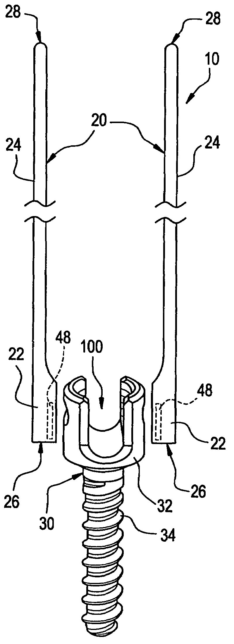
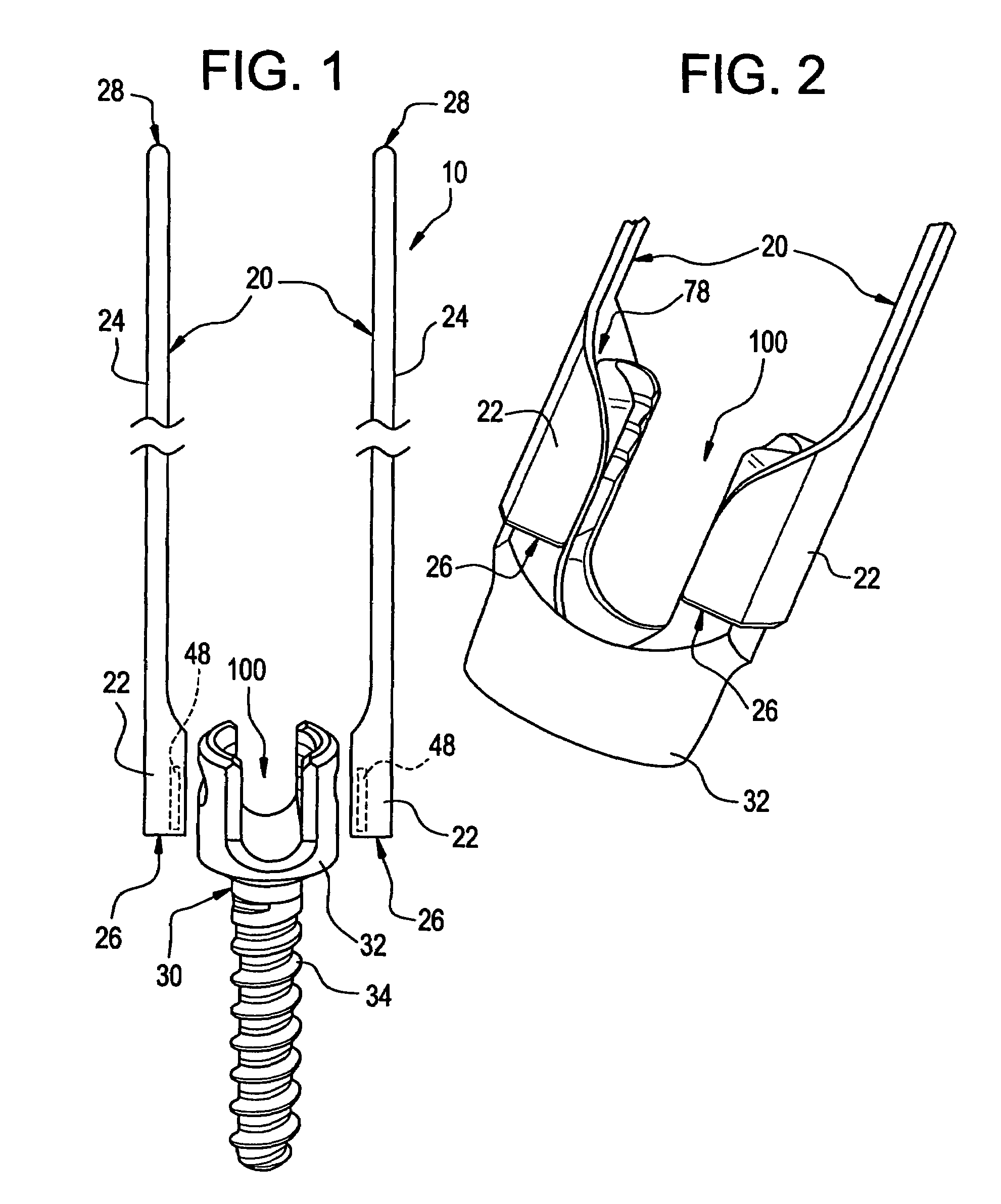
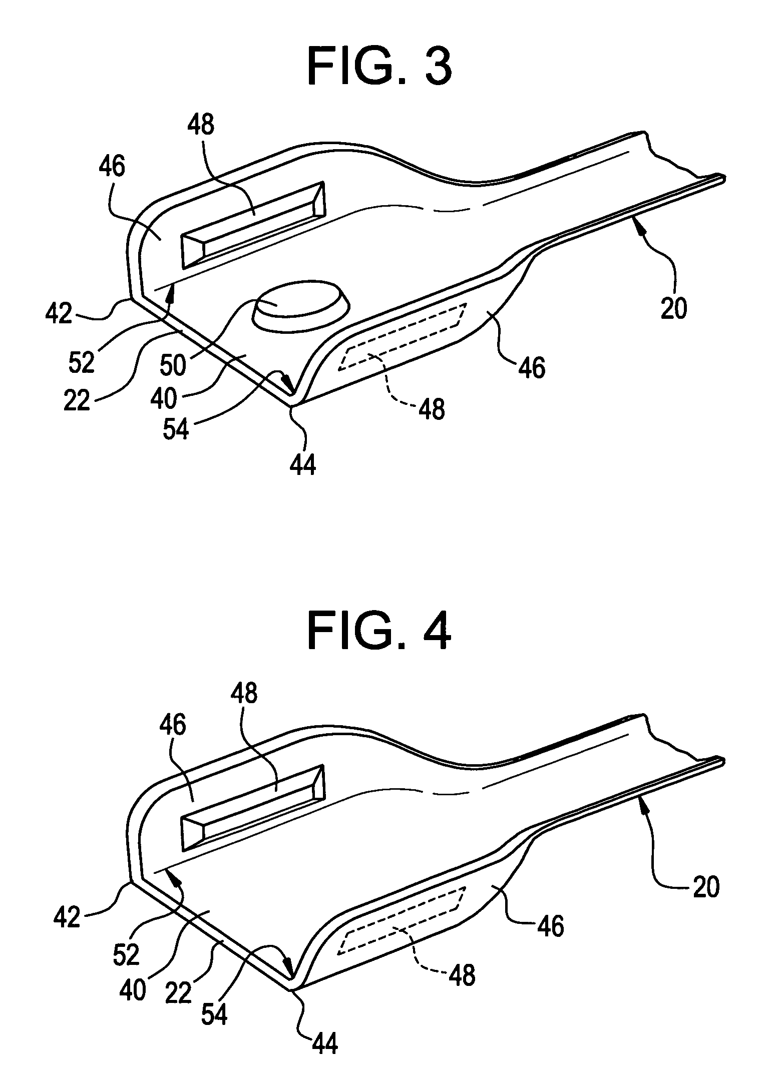
[0030]As shown in FIG. 1, one embodiment of the surgical system 10 includes extenders 20 that can be releasably attached to a bone anchor 30. In one embodiment, the mechanism for releasably attaching the extenders 20 to the bone anchor 30 includes clipping the extenders 20 to the bone anchor 30. Each of the extenders 20 includes a clip 22 located...


PUM


Abstract

An apparatus is provided for guiding a surgical implant to a bone anchor during surgery. The apparatus includes a bone anchor extender releasably attachable to the bone anchor wherein the bone anchor extender clips onto a head portion of the bone anchor to assist in guiding the surgical implant to the bone anchor.

Description

BACKGROUND OF THE INVENTION[0001]The present invention relates to surgical devices and methods and more particularly, but not exclusively, to fixation element extension devices for use during surgical procedures.[0002]Several surgical procedures utilize fixation elements that can be secured to bone or bony structures. These fixation elements can be used to apply stabilizing or corrective forces to the bone or bony structures. A wide variety of fixation elements are provided that are specifically designed to connect to or engage in various bones or bony structures. For example, such fixation elements can include bone screws, posts or spikes that can be anchored into various bones or bony structures. In addition, another fixation element is a hook that is configured to engage the laminae of the vertebra. More specifically, even other fixation elements include spinal screws or bolts having threaded sections that are configured to be anchored in vertebral bone. With reference to spinal ...

Claims


Application Information

Patent Timeline
Patent Type & Authority Patents(United States)
IPC IPC(8): A61B17/56
CPCA61B17/7082A61B17/7085A61B17/7091A61B17/7011A61B17/7032
Inventor POND, JR., JOHN D.MELKENT, ANTHONY J.BRUNEAU, AURELIEN
Owner WARSAW ORTHOPEDIC INC
Why Eureka
Try Eureka