Vehicle exterior mirror assembly with blind spot indicator

a technology for exterior mirrors and blind spots, applied in the direction of instruments, analogue processes for specific applications, electric/magnetic computing, etc., can solve the problems of confusion of the driver of the host vehicle, difficulty in determining the driver of the other vehicle, and the construction of blind spot indicators that are somewhat costly and complicated, etc., to achieve easy to view, easily viewable, and easily visible

Active Publication Date: 2009-02-17
DONNELLY CORP
View PDF82 Cites 283 Cited by
  • Summary
  • Abstract
  • Description
  • Claims
  • Application Information

AI Technical Summary

Benefits of technology

[0011]The blind spot indicator may include a light source or illumination source (such as one or more light emitting diodes (LEDs) or the like), and may include a lens or other optic or light directing / guiding device or element or means or a light channel, conduit or means, or a light baffle or means, or a light louver or blind or means, or a light directing element or means, preferably at the mirror shell or casing (and substantially disposed therein so as not to overly protrude to create aerodynamic drag and so as to provide an aesthetically pleasing exterior appearance) for directing the light emitted by the light source toward the driver for viewing by the driver of the host vehicle and, if required, for limiting or restricting viewing by drivers of other vehicles.
[0017]Therefore, the present invention provides a blind spot indicator at an inboard wall or portion of an exterior rearview mirror assembly. The blind spot indicator is located at an inboard wall or portion of the mirror casing or shell or at an inboard support arm or the like of the mirror assembly and, thus, is readily viewable by the driver of the host vehicle, and without the driver having to look across to the outboard dimension of the mirror reflective element to see or notice actuation or illumination of the blind spot indicator. The blind spot indicator thus may be readily viewable by the driver and may be so viewable without the driver having to look at the reflective element of the exterior mirror to see the blind spot indicator. Also, because the blind spot indicator is located at the inboard portion of the mirror assembly, the blind spot indicator is viewable principally or solely by the driver of the host vehicle, and is not readily viewable or visible to a driver of another vehicle. Because the blind spot indicator is not located at a primary viewing area, the curb-side appeal or appearance of the vehicle is not adversely impacted by the choice and styling of the blind spot indicator. Also, because the blind spot indicator of the present invention is not located behind a window in the reflective element, or behind a transflective portion of the reflective element, the blind spot indicator may be fixedly placed and may provide a low cost indicator that may be readily incorporated into an exterior rearview mirror assembly of a vehicle.

Problems solved by technology

It is known to provide a blind spot detection / LCA system for a vehicle that detects the presence of another vehicle or object in the lane next to the host vehicle, where it may be difficult for the driver of the host vehicle to determine whether or not there is another vehicle or object adjacent to the host vehicle.
If the indicator is located external to the vehicle cabin, and especially since it is now common to use turn signals on exterior mirrors, any visibility of the indicator to the driver of another vehicle (such as a trailing vehicle or an overtaking vehicle) may cause confusion to the driver of the other vehicle as to whether or not the indicator is a turn signal indicator or some other vehicle lighting or the like.
This may be particularly problematic when the blind spot indicator is located behind (and often supported by) the reflective mirror element of the vehicle exterior mirror assembly, and may be especially confusing if other indicators are also disposed behind / supported by the mirror reflective element so as to function, for example, as turn signal indicators.
For example, somewhat costly and complicated blind spot indicator constructions have been contemplated that, when placed behind and supported by the mirror reflective element, attempt to have their projected beam of emitted light shielded from view by other drivers and attempt to be directed principally to be viewed by the driver of the host vehicle.
These prior art blind spot / LCA indicators thus are not provided at a universally controllable angle or fixed angle relative to the geometry of the vehicle and thus may not be optimally directed for viewing by some drivers, depending on the desired and set angle of the mirror reflective element for the particular driver of the host vehicle and / or may not be optimally directed for non-viewing by drivers of other vehicles, such as trailing or overtaking vehicles that are part of the traffic encountered by the host vehicle.

Method used


Image

  • Vehicle exterior mirror assembly with blind spot indicator
  • Vehicle exterior mirror assembly with blind spot indicator
  • Vehicle exterior mirror assembly with blind spot indicator

Examples


Embodiment Construction

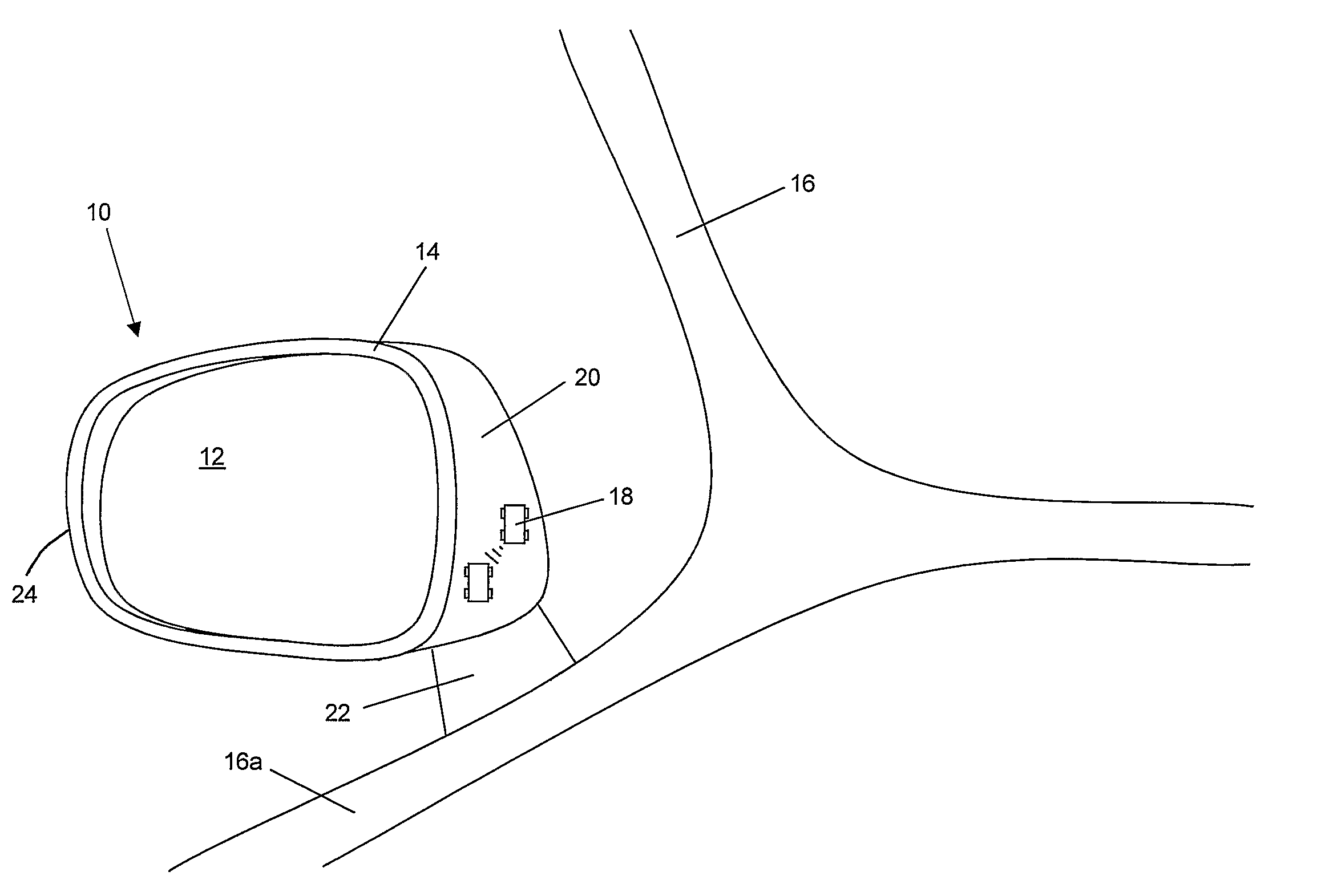
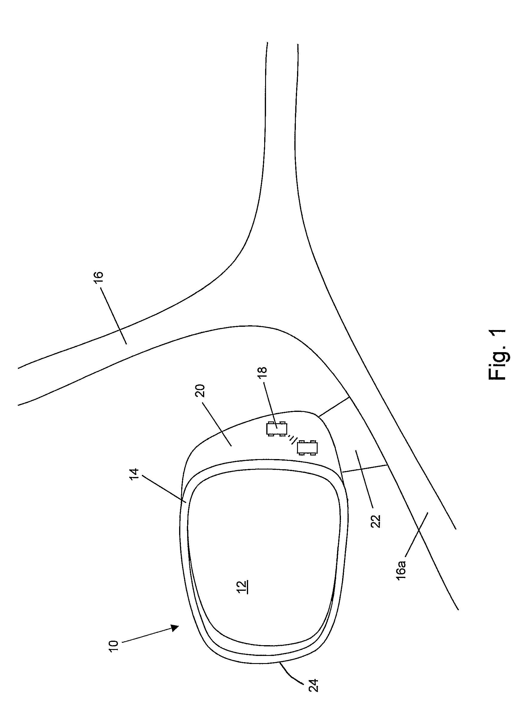
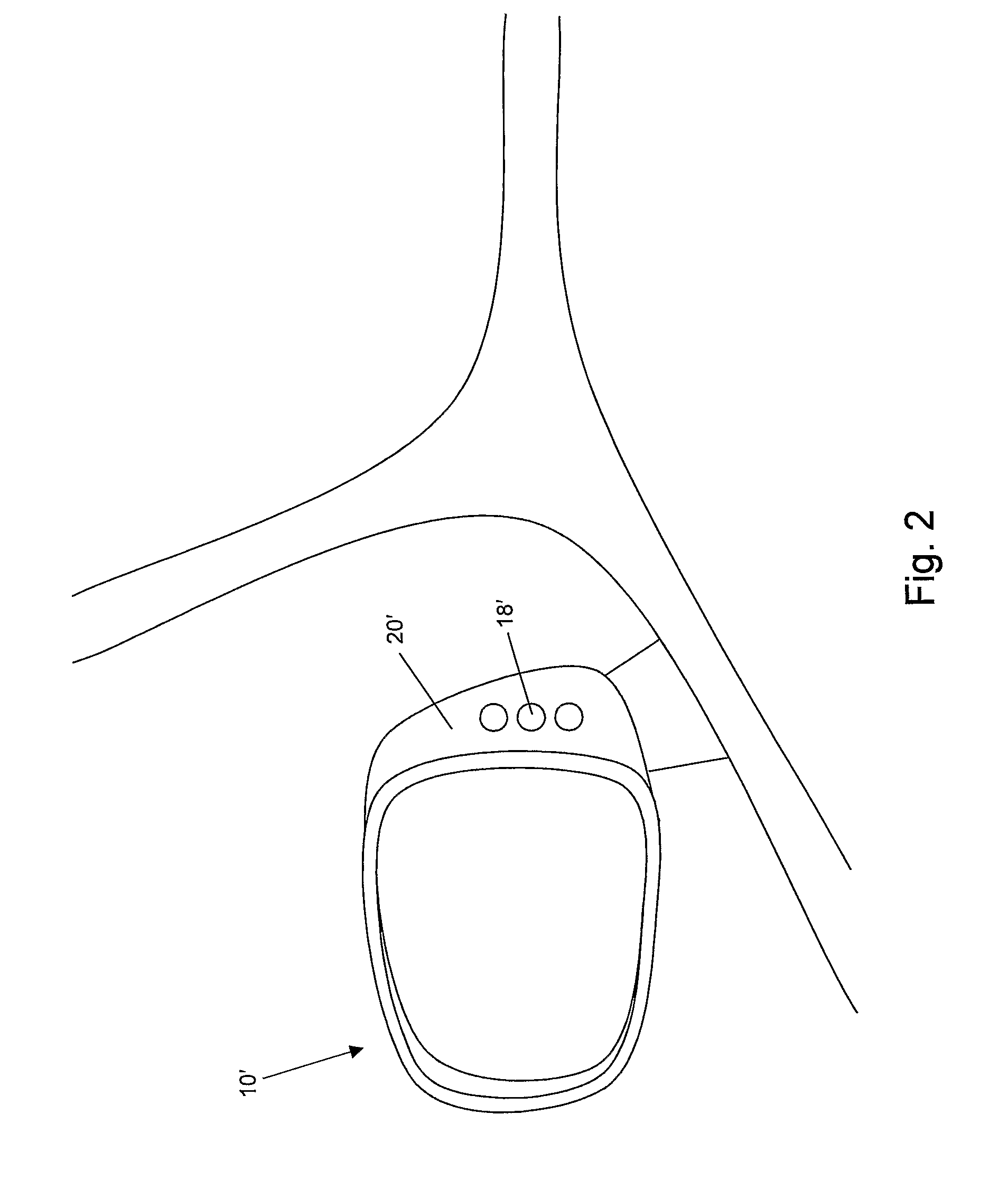
[0051]Referring now to the drawings and the illustrative embodiments depicted therein, an exterior rearview mirror assembly 10 for a vehicle includes a reflective element 12 and a mirror shell or casing 14 (FIG. 1). Mirror assembly 10 is mounted at the side 16a of a host or subject vehicle 16, and includes a blind spot indicator 18 at an inboard portion 20 of mirror assembly 10. The blind spot indicator 18 is operable by illumination to indicate to the driver of the subject or host vehicle that an object or other vehicle is detected at the side or blind spot region of the host vehicle by a blind spot detection system, as discussed below. The indicator may be activated or energized in response to a detection of an object or other vehicle approaching or adjacent to the host vehicle in order to alert or warn the driver of the host vehicle not to attempt or initiate a lane change that moves the subject or host vehicle into the already occupied (or soon to be occupied) side lane or regio...


PUM


Abstract

An exterior rearview mirror system for a vehicle includes an exterior mirror assembly that is mountable at an exterior side of a vehicle and has an inboard portion that is viewable by a driver of the vehicle when the mirror assembly is mounted at the exterior side of the vehicle. A blind spot indicator is disposed at the inboard portion of the mirror casing of the mirror assembly. The blind spot indicator comprises at least one illumination source for indicating to the driver a detected presence of an object alongside of and / or rearward of the vehicle. The indicator may comprise a unitary indicator module that is mountable at the inboard portion of the mirror assembly. The indicator module includes an illumination source and circuitry and is connectable to an electrical connector.

Description

CROSS REFERENCE TO RELATED APPLICATIONS[0001]The present application is a 371 national phase application of PCT Application No. PCT / US2006 / 026148, filed Jul. 5, 2006, which claims benefit of U.S. provisional applications, Ser. No. 60 / 696,953, filed Jul. 6, 2005; and Ser. No. 60 / 784,570, filed Mar. 22, 2006, which are hereby incorporated herein by reference in their entireties.FIELD OF THE INVENTION[0002]The present invention relates to exterior rearview mirror assemblies and, more particularly, to an exterior rearview mirror assembly having a blind spot indicator and / or a lane change aid (LCA) indicator at the mirror assembly.BACKGROUND OF THE INVENTION[0003]It is known to provide a blind spot detection / LCA system for a vehicle that detects the presence of another vehicle or object in the lane next to the host vehicle, where it may be difficult for the driver of the host vehicle to determine whether or not there is another vehicle or object adjacent to the host vehicle. Such a blind...

Claims


Application Information

Patent Timeline
Patent Type & Authority Patents(United States)
IPC IPC(8): G08G1/00G06F17/10
CPCB60Q1/2665B60R1/1207B60R2001/1215B60R2001/1223
Inventor LYNAM, NIALL R.RUSE, JAMES A.KENDALL, CRAIG
Owner DONNELLY CORP
Why Eureka
Try Eureka