AFCI temperature compensated current sensor

a current sensor and temperature compensation technology, applied in the direction of emergency protective circuit arrangement, emergency protection circuit arrangement, etc., can solve the problem of providing no galvanic isolation, arcing fault condition to be undetected by a circuit breaker, and undetected arcing fault condition

Inactive Publication Date: 2009-02-17
SIEMENS ENERGY & AUTOMATION INC
View PDF132 Cites 13 Cited by
  • Summary
  • Abstract
  • Description
  • Claims
  • Application Information

AI Technical Summary

Benefits of technology

[0007]It is also an object of the present invention to provide an improved sense resistor that is inexpensive, accurate, responds at high frequencies, and imparts galvanic isolation at varying ambient temperatures.

Problems solved by technology

Arcing faults may be undetected by standard circuit breakers, because the current flow may be below the breaker's tripping threshold.
Upon occurrence of an arcing fault, branch or load impedance may cause the current levels to be reduced to a level below the trip curve setting of the circuit breaker, causing the arcing fault condition to be undetected by a circuit breaker.
However, a disadvantage of the sense resistors is that they provide no galvanic isolation.
Another disadvantage is that the sensor output signal tends to vary with temperature variations.
Known sense resistor configurations do not compensate the current for this variance in ambient temperature.
However, both current transformers and Hall Effect sensors are more expensive solutions.
Further, the frequency content for current transformer and Hall Effect sensors will be lost or will be filtered out because they have a low pass filter type transfer function.
A disadvantage of a low pass filter type transfer function is that the critical information of the frequency content provided at higher frequencies will be missed.
A further disadvantage of current transformers is that they occupy a relatively large area of a printed circuit board.

Method used


Image

  • AFCI temperature compensated current sensor
  • AFCI temperature compensated current sensor
  • AFCI temperature compensated current sensor

Examples


Embodiment Construction

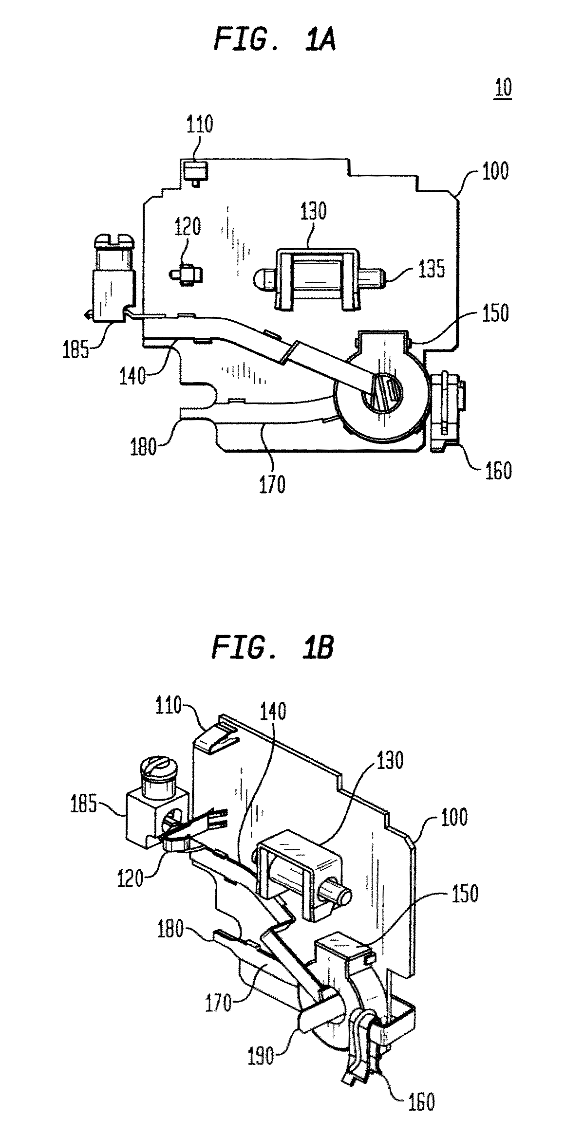
[0019]FIG. 1a) refers to the components incorporated in a powered circuit 10 comprising a printed circuit board 100 comprising push to test switches 110, power clip 120, solenoid 130, part of neutral trace 140, differential sensor 150, line terminal 160, sense resistor 170, neutral pigtail 180, neutral lug 185, and contact 190. Power clip 120 connects printed circuit board 100 to a voltage source.

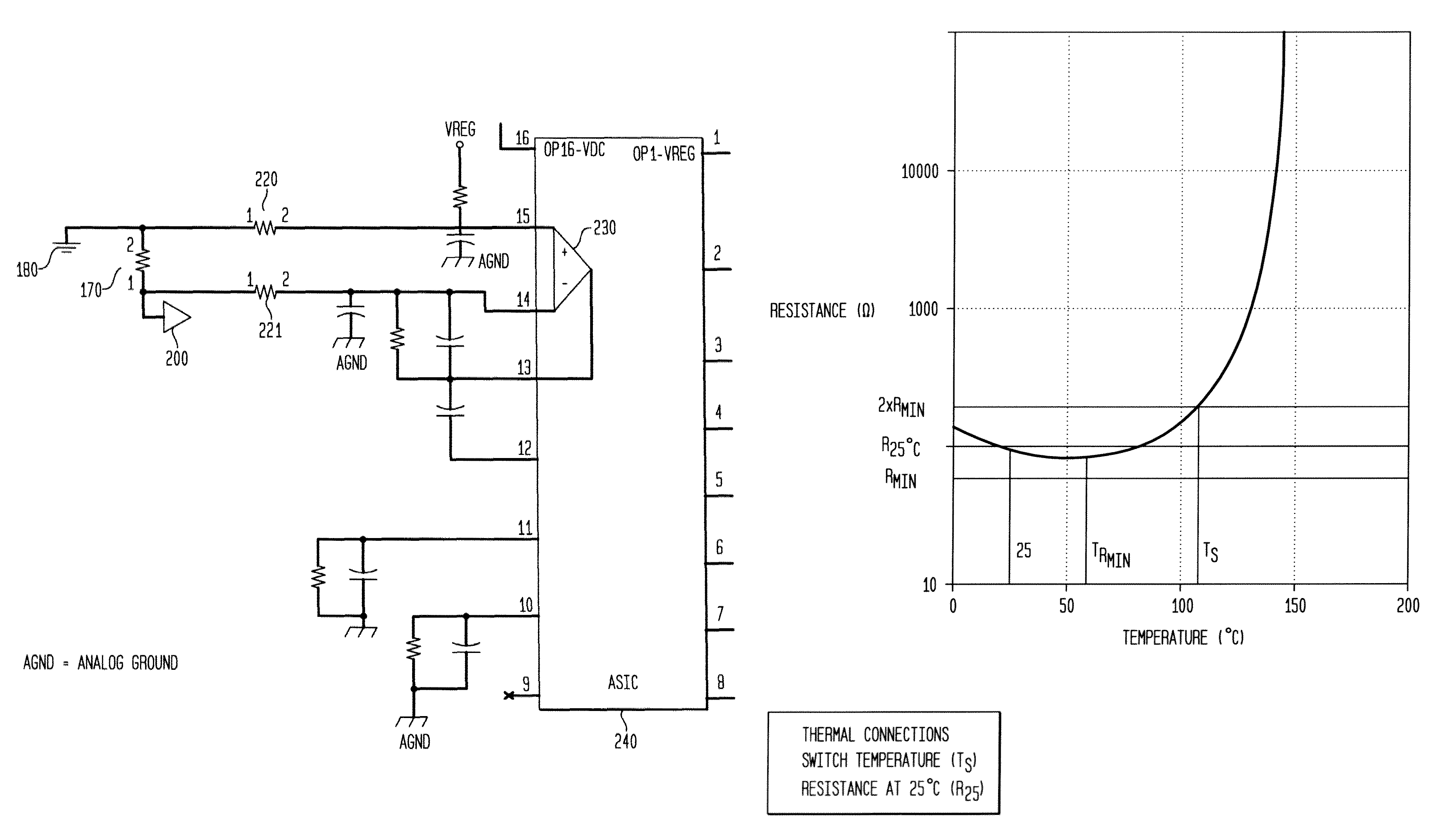
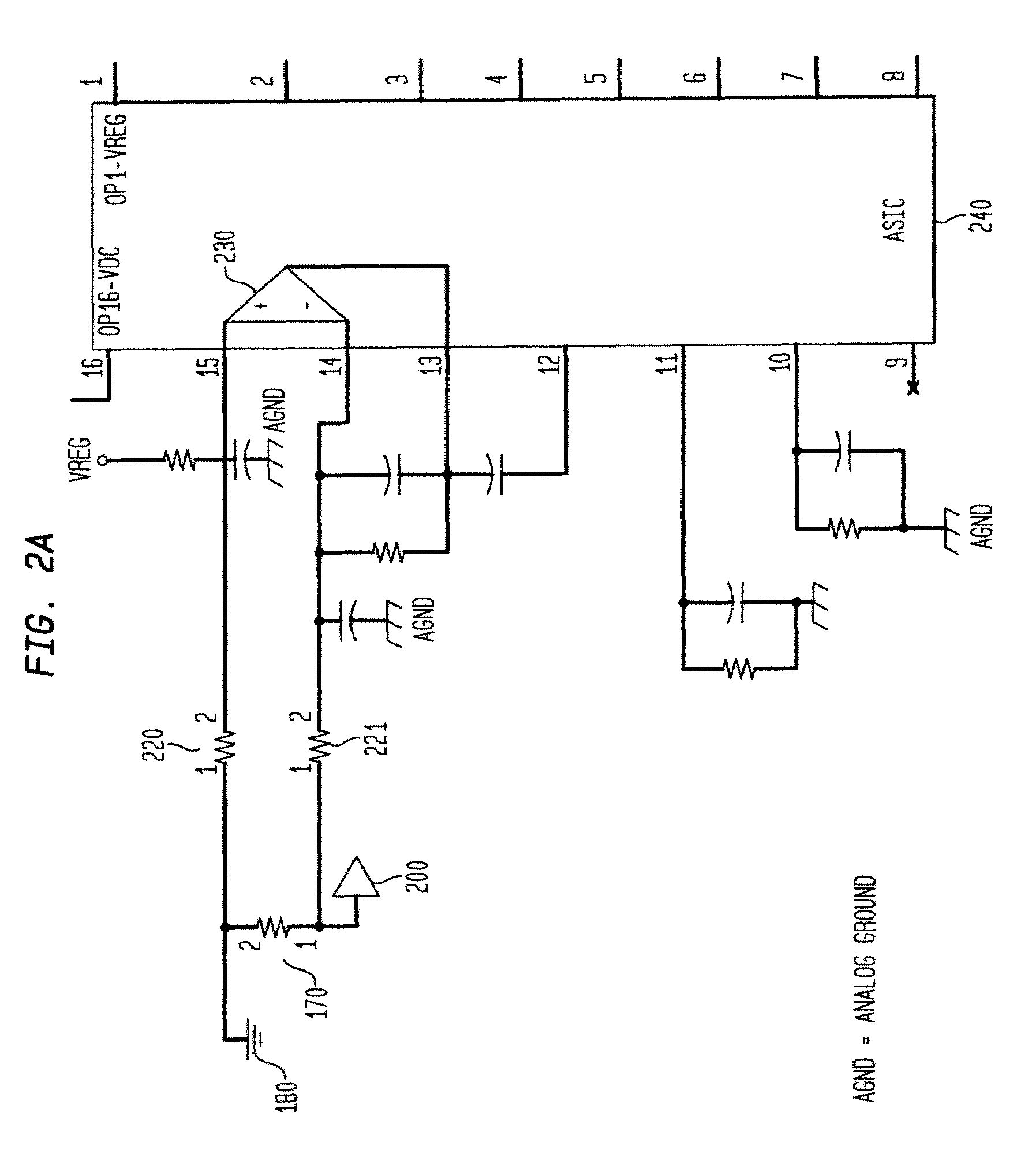
[0020]Current is sensed when a proportional voltage signal is generated by the passage of current through the sense resistor 170. By switching on a load, a current is first sent through the partial of neutral trace 140 to the differential sensor 150. The differential sensor 150 is used to detect hot to neutral situational arcs to safeguard ground wire devices. Solenoid 130 comprises a plunger 135 that extends upon reaction and detection of a hot to neutral situational arc by differential sensor 150. From the differential sensor 150, the current flows to the sense resistor 170 and then out t...


PUM


Abstract

An apparatus and method for thermally compensating a voltage signal for a circuit protection device. The circuit protection device is coupled to a powered circuit and having current flowing through it. A bus carries the power therethrough. A sense resistor is electrically coupled to a bus for sensing the current flowing through the bus. A temperature sensitive circuit is coupled to the sense resistor for compensating ambient temperatures. The invention is useful for providing an accurate sense resistor that supplies a temperature independent current in a power line and the related voltage output of the sense resistor at varying ambient temperatures.

Description

FIELD OF INVENTION[0001]The present invention relates to an apparatus and method for sensing and translating a current signal into a temperature compensated voltage signal used by an Arc Fault Circuit Interrupter (AFCI) detection circuitBACKGROUND[0002]In general, several different types of sensing apparatus have been used to measure current in an electrical circuit. Such sensing apparatus may utilize sense resistors, current transformers, and Hall Effect sensors. These sensors are used to monitor and measure current as it is passes through the load of a circuit either for purposes of overcurrent protection or to control another circuit based on the measured current in the load.[0003]Sensors are also used to detect wave forms and the shape of current which can indicate the presence of an arc fault. Arcing faults may be defined as the existence of a current path between two ends of a broken conductor located within an ionized gas, between two conductors supplying a load, or between a...

Claims


Application Information

Patent Timeline
Patent Type & Authority Patents(United States)
IPC IPC(8): H02H5/04H02H3/00G01R19/32
CPCG01R19/32
Inventor EVANS, TERY JOHNJOHNSON, ELTON C.RESTREPO, CARLOS
Owner SIEMENS ENERGY & AUTOMATION INC
Why Eureka
Try Eureka