Controllable motorized device for percutaneous needle placement in soft tissue target and methods and systems related thereto

Inactive Publication Date: 2009-02-24
THE JOHN HOPKINS UNIV SCHOOL OF MEDICINE
View PDF13 Cites 53 Cited by
  • Summary
  • Abstract
  • Description
  • Claims
  • Application Information

AI Technical Summary

Benefits of technology

[0015]According to a third aspect of the present invention, the first arm is further configured and arranged to releasably support the penetrating member distal portion and the second arm guide portion releasably receives the penetrating member therein. In a more particular embodiment, each of the first and second members is further configured and arranged so as to include a releasable segment that is releasably secured to the other portion of the arm. In more particular embodiments, the apparatus further includes a release-grasp mechanism that is configured and arranged to secure the releasable segment to its arm and to de-secure the release segment upon some action by the surgical personnel. In a more specific embodiment, such de-securing occurs automatically when certain conditions (e.g., power failure) is determined to exist.
[0016]According to a fourth aspect of the present invention, the apparatus further includes the penetrating member, which penetrating member is configured an arranged so as to perform any of a number of techniques, protocols, surgical techniques or therapeutic techniques. These include

Problems solved by technology

A fundamental problem in clinical delivery of percutaneous therapy and needle biopsy is precise placement of the percutaneous needle in inhomogenous soft tissue.
In conventional systems and methods, the targeting accuracy exceeds and often greatly exceeds the driving accuracy that can be achieved.
Furthermore, a wide spectrum of treatment methods require that the percutaneous needle be held firmly in the target location for a considerable period of time while the patient is in repiratory, cardiac and muscular motion.
For example, then existing radiologic

Method used


Image

  • Controllable motorized device for percutaneous needle placement in soft tissue target and methods and systems related thereto
  • Controllable motorized device for percutaneous needle placement in soft tissue target and methods and systems related thereto
  • Controllable motorized device for percutaneous needle placement in soft tissue target and methods and systems related thereto

Examples


Embodiment Construction

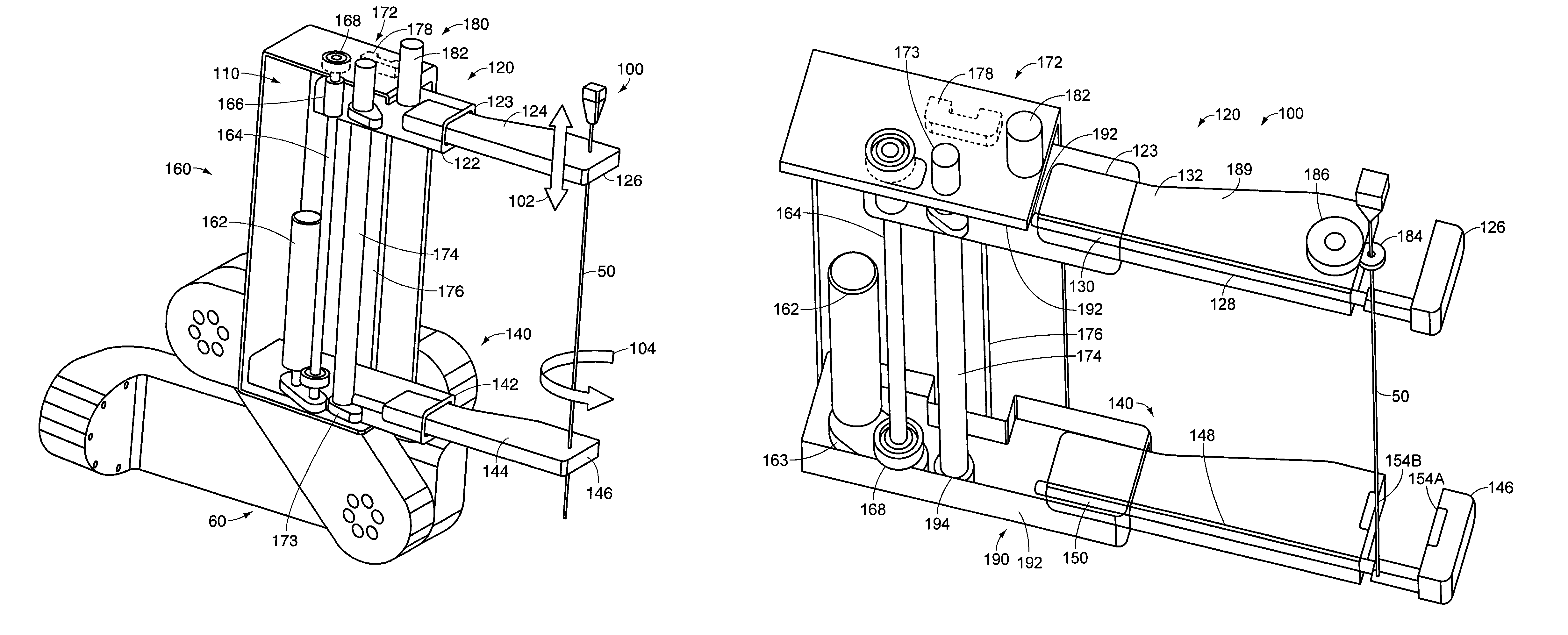
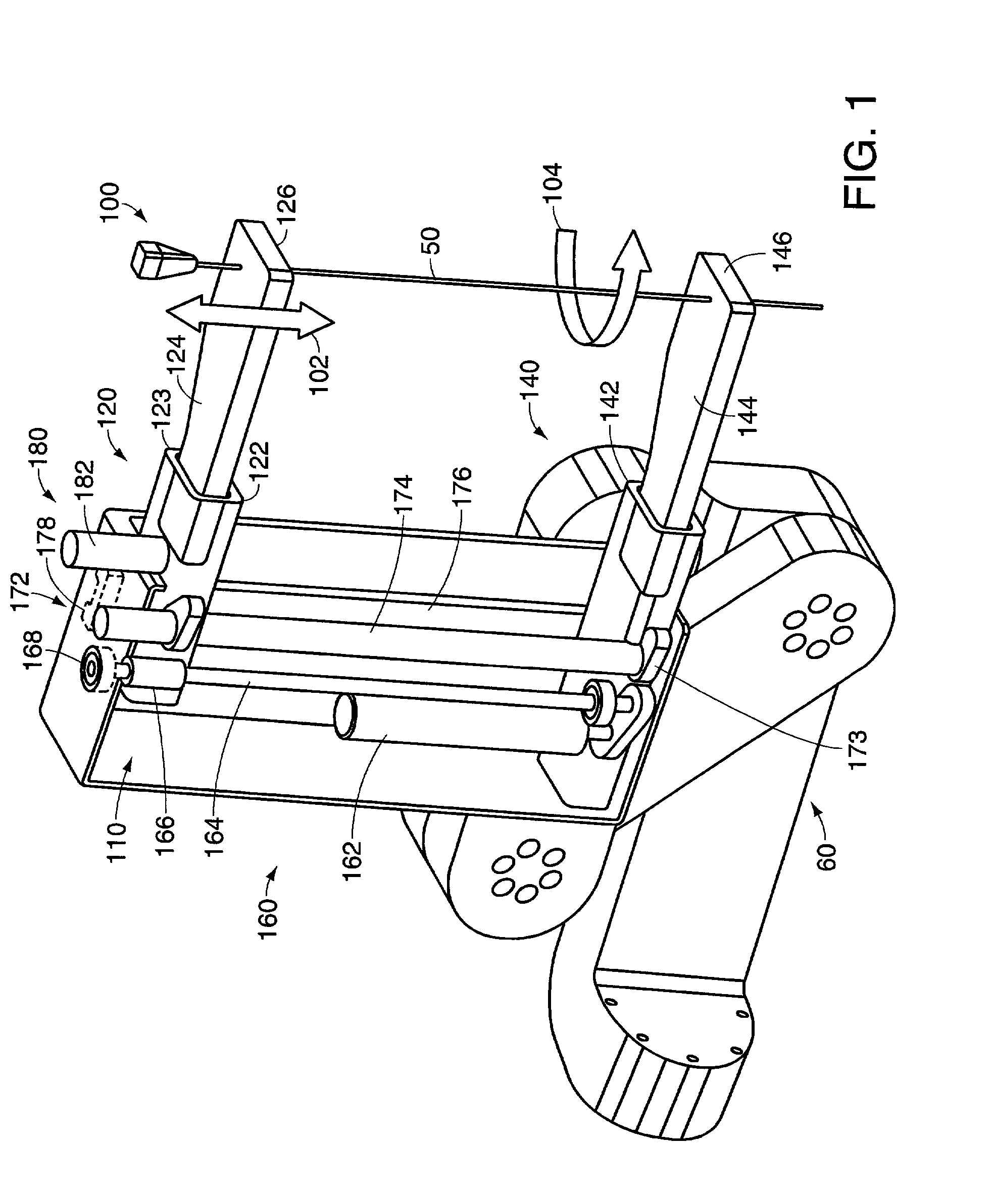
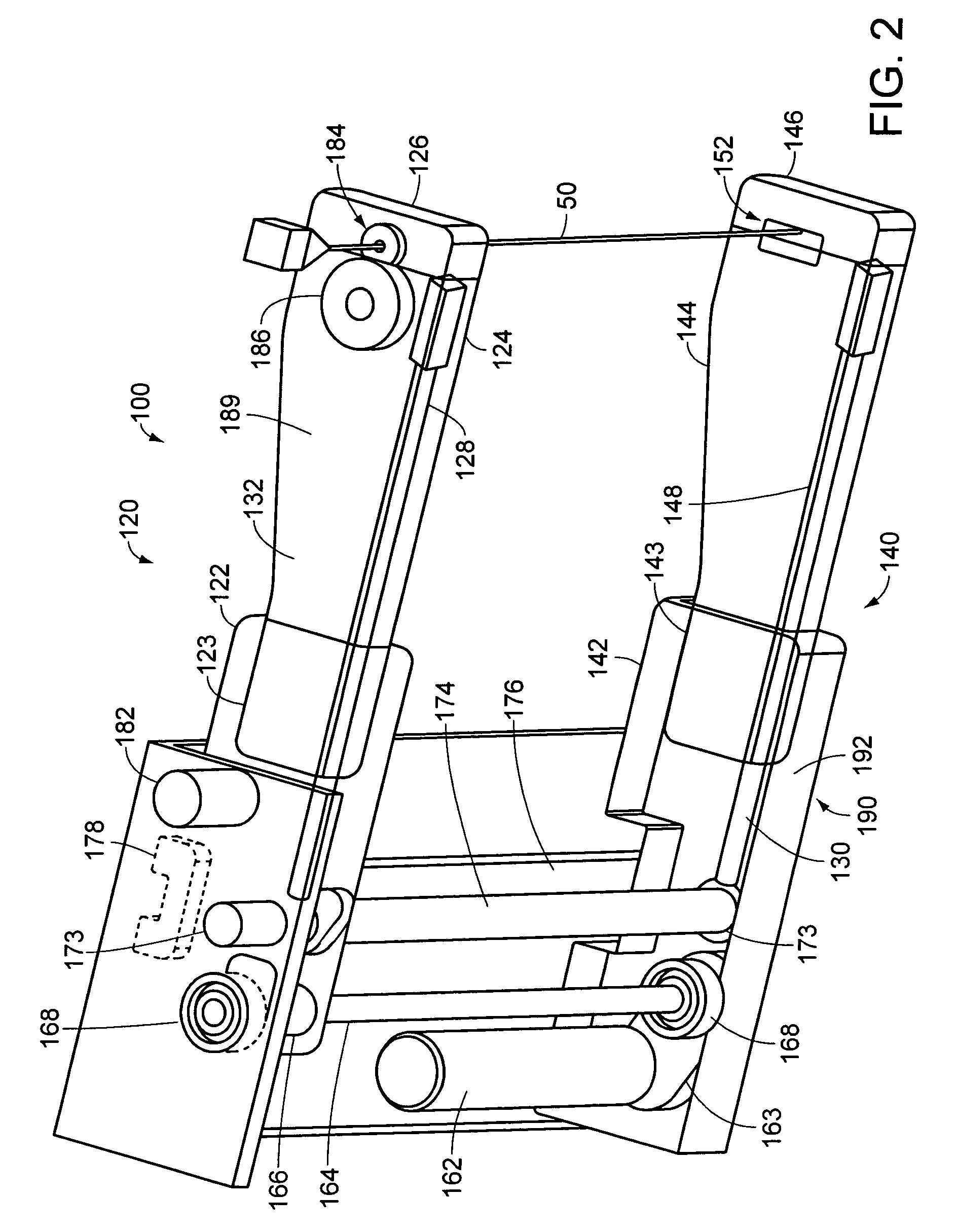
[0029]Referring now to the various figures of the drawing wherein like reference characters refer to like parts, there is shown in FIGS. 1-5 various views of a penetrating member driver 100 according to the present invention particularly configured and arranged for driving a penetrating member, such as a needle 50, into a target area of soft tissue of a body. These figures also illustrate various in process configurations of the penetrating member driver 100 as well as illustrating its use in connection with a member 60 of any of a number of manual, motorized or robotic targeting apparatuses or systems as is known to those skilled in the art. In use these manual, motorized or robotic targeting apparatuses or systems are operated so the needle 50 axis being held in the penetrating member driver 100 is positioned and oriented so that it points at the entry point of the body and also so that the needle is oriented such that it translates along the translational axis to the target area....


PUM


Abstract

Featured is an apparatus that places or locates a proximal end portion of a penetrating member in a target area of a body. Such an apparatus or needle driver is particularly suited for locating a percutaneous needle in a soft tissue target area of a body particularly a body having inhomogeneous soft tissues. The apparatus includes a first arm that is configured and arranged so as to support a distal portion of the penetrating member and a first drive mechanism that is coupled to the first arm. The first drive mechanism is configured and arranged to move or translate the first arm from an initial position to any of a number of other positions that are spaced from the initial position and correspondingly translate the proximal end portion of the penetrating member. In another embodiment, the first arm also rotatably supports the penetrating member and the apparatus further includes a second drive mechanism coupled to the penetrating member distal portion and which is configured an arranged to rotate the penetrating member about the translational axis.

Description

[0001]This application claims the benefit of U.S. Provisional Application Ser. No. 60 / 228,993 Aug. 30, 2000, the teachings of which are incorporated herein by reference.STATEMENT OF GOVERNMENT INTEREST[0002]Funding for the present invention was provided in part by the Government of the United States by virtue of Grant No. EEC9731478 by the National Science Foundation. Thus, the Government of the United States has certain rights in and to the invention claimed herein.FIELD OF INVENTION[0003]The present invention relates to methods, systems and devices for percutaneous surgery and more particularly to a controllable, motorized device for percutaneous needle placement in a soft tissue target including systems and methods related thereto.BACKGROUND OF THE INVENTION[0004]As an alternative to traditional surgical techniques or methodologies, percutaneous surgery has been found to significantly reduce morbidity and post-operative recovery time. A fundamental problem in clinical delivery of...

Claims


Application Information

Patent Timeline
IPC IPC(8): A61B19/00A61B17/00
CPCA61B19/26A61B19/203A61B19/22A61B2017/00115A61B2017/00119A61B34/70A61B90/14A61B90/50
Inventor STOIANOVICI, DANFICHTINGER, GABORWIARD, RICHARD MATTHEWIORDACHITA, IOAN JULIANWHITCOMB, LOUIS LITCHFIELDTAYLOR, RUSSELL H.
Owner THE JOHN HOPKINS UNIV SCHOOL OF MEDICINE
Why Eureka
Try Eureka