Electrostatic atomizing device and humidifier using the same

a technology of electrostatic atomization and humidifier, which is applied in the direction of lighting and heating apparatus, heating types, separation processes, etc., can solve the problems of requiring regular maintenance of removing precipitants, and achieve the effect of stable electrostatic atomization

Inactive Publication Date: 2009-02-24
MATSUSHITA ELECTRIC WORKS LTD
View PDF14 Cites 34 Cited by
  • Summary
  • Abstract
  • Description
  • Claims
  • Application Information

AI Technical Summary

Benefits of technology

[0003]The present invention has been achieved to overcome the above problem and to present an electrostatically atomizing device and the humidifier using the same which can avoid the precipitation of impurities contained in the liquid at the discharge end of the carrier for maintaining stable electrostatic atomization over a long period of use.
[0004]The electrostatically atomizing device of the present invention includes a carrier having a liquid collecting end and a discharge end opposite of the liquid collecting end, the liquid collecting end collecting a liquid for feeding the liquid to the discharge end. The device includes a first electrode, a second electrode, and a voltage source. The voltage source applies a voltage across the first and second electrodes to charge the liquid at the discharge end, thereby emitting the liquid in the form of tiny ionized particles. The characterizing feature of the present invention is to include a steam supply which feeds a steam to the liquid collecting end of the carrier for condensation of the liquid therearound in order that the condensed liquid is fed to the discharge end of the carrier. Thus, even with the use of the liquid in which cation of Ca or Mg is dissolved, the content of Ca or Mg cation can be minimized by the effect of steam, thereby inhibiting the impurities from being fed to the discharge end of the carrier and avoiding the lowering of the electrostatic atomization by the precipitation of the impurities. Accordingly, frequent cleaning of the discharge end can be avoided to keep the stable electrostatic atomization over a long period of use.
[0006]The condensation compartment is preferably configured to make a circular flow of the steam around the liquid collecting end of the carrier. The circular flow increases the chance of contact between the steam and the carrier to improve condensation effect by cooling of the steam, assuring to feed the liquid stably to the discharge end of the carrier.
[0008]Further, the electrostatically atomizing device is preferred to include a fan producing a forced air flow, and an air duct introducing the forced air flow into between the discharge end and the second electrode. With this arrangement, the tiny ionized particles of the liquid generated between the discharge end and the second electrode is carried on the forced air flow to spread over a wide range. In this case, a baffle may be provided to shield the carrier from the forced air flow, avoiding undue evaporation of the liquid from the carrier.
[0009]Thus configured electrostatically atomizing device is preferably incorporated into an appliance such as a humidifier. The humidifier has a fan generating an forced air flow and a steam path for directing a portion of the steam from the steam supply as being carried on the forced air flow and emitting the steam outwardly. Consequently, in addition to general humidification effect by the steam, the tiny ionized particles of the liquid can be dispersed to improve skin beauty effect due to high skin penetration capability that the tiny ionized particles exhibit, as well as room deodorizing effect.

Problems solved by technology

Therefore, it has been a problem to require maintenance of removing the precipitants regularly.

Method used


Image

  • Electrostatic atomizing device and humidifier using the same
  • Electrostatic atomizing device and humidifier using the same
  • Electrostatic atomizing device and humidifier using the same

Examples


Embodiment Construction

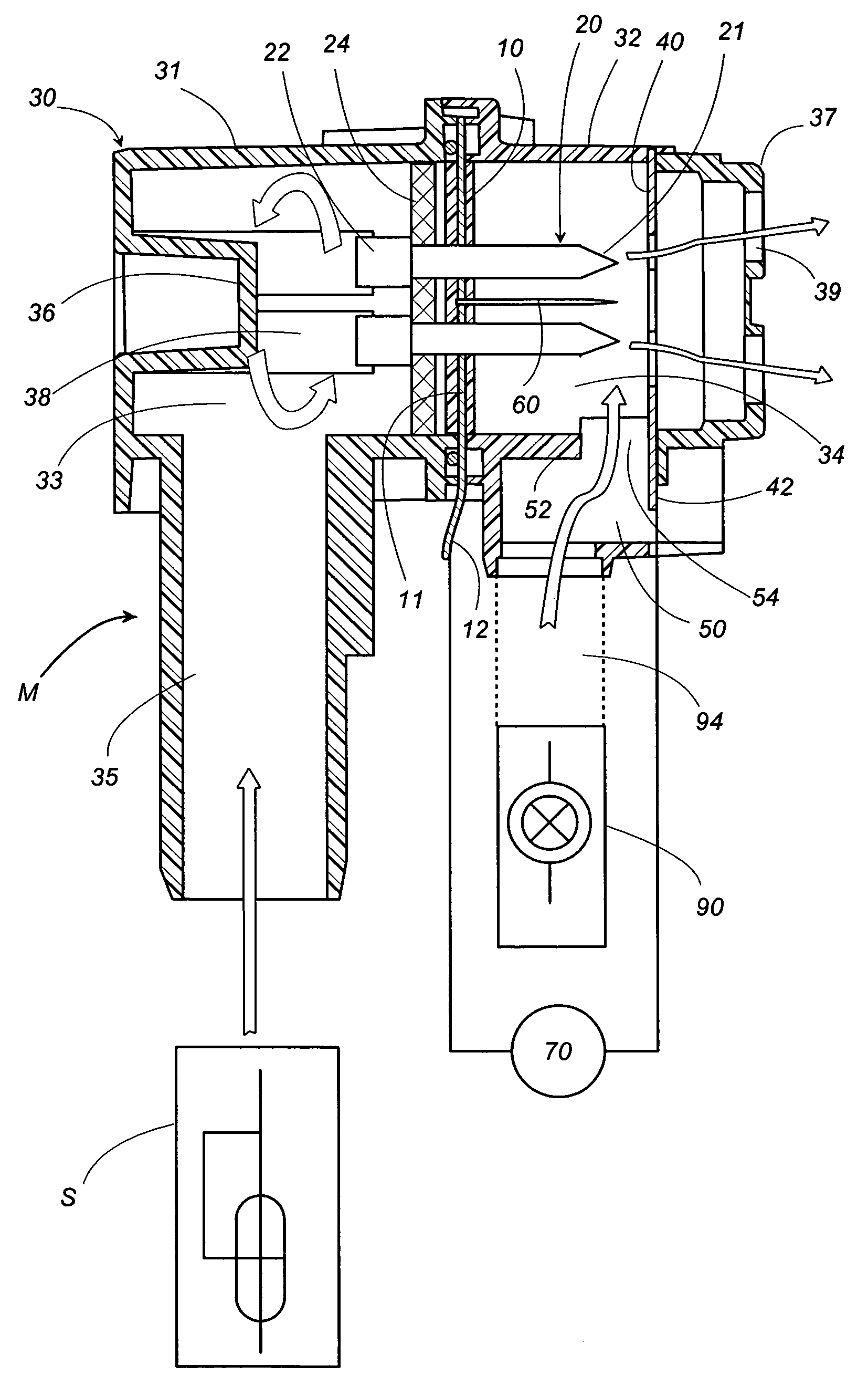
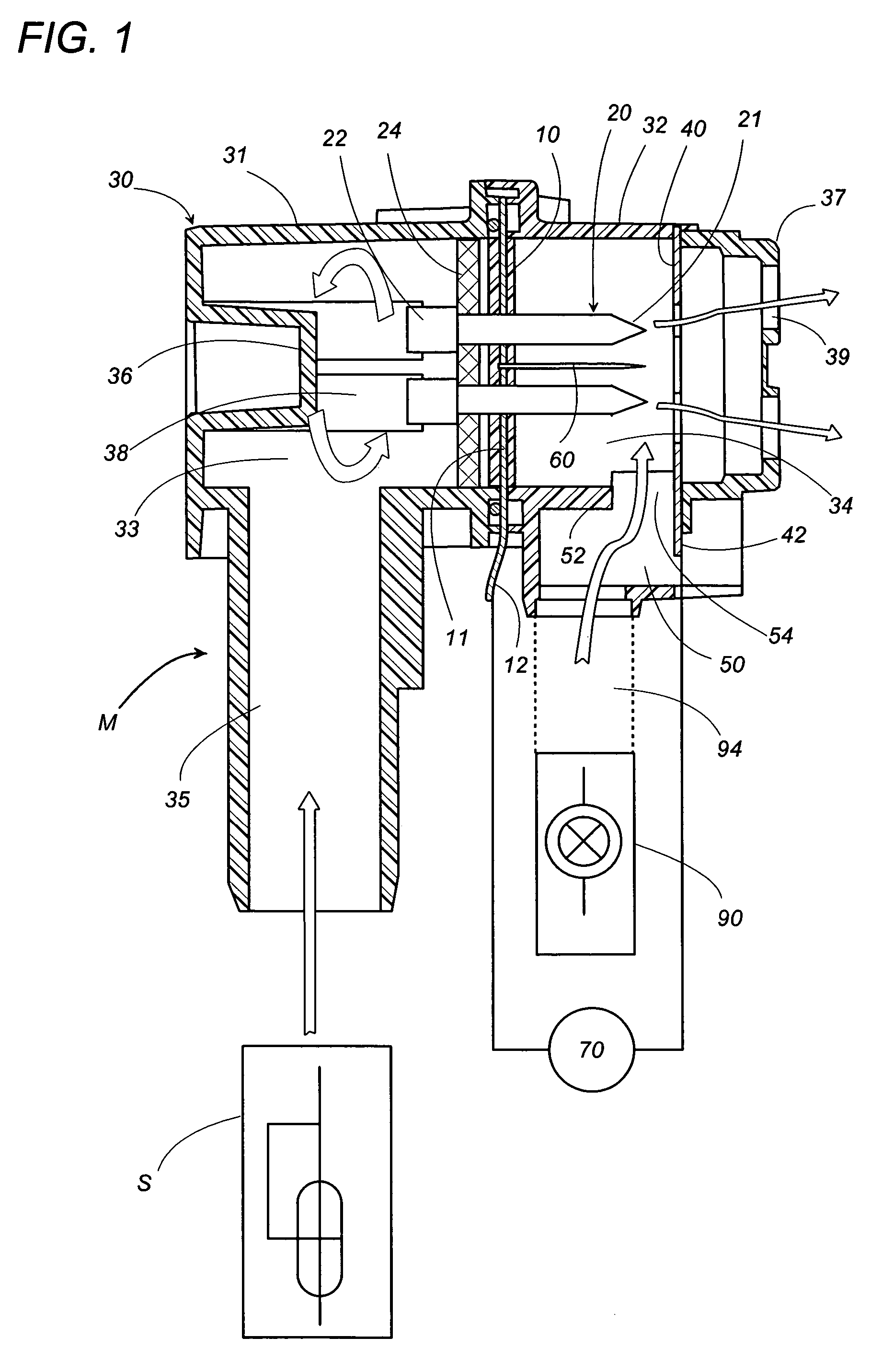
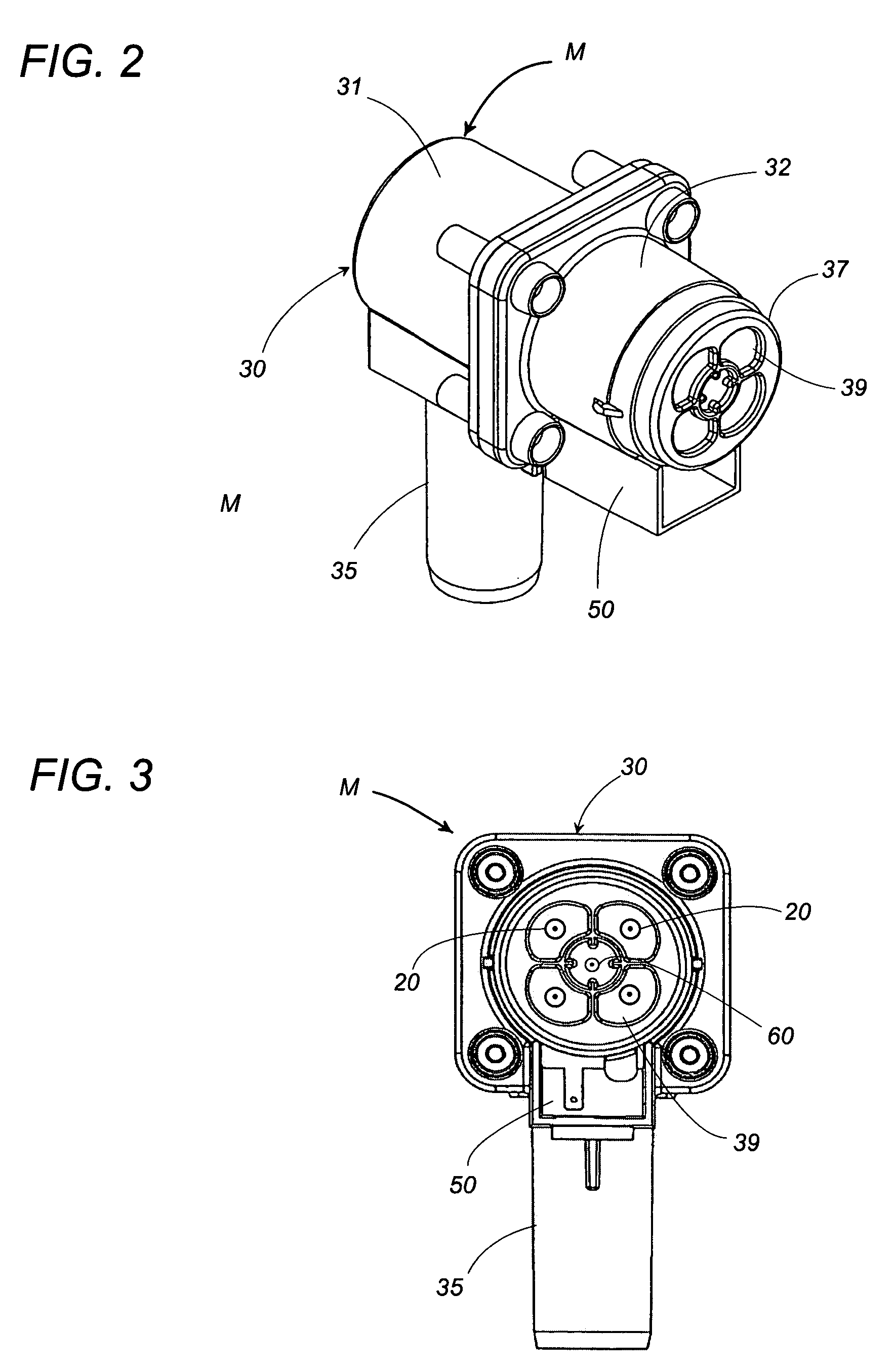
[0019]An electrostatically atomizing device in accordance with one embodiment of the present invention is configured to ionize particulate water, for example, so as to generate ionized water particles of a nanometer size, and include an atomizing unit M for electrostatically atomizing the liquid, and a steam generator S providing a steam of water. As shown in FIG. 1, the atomizing unit M includes a case 30 accommodating a plurality of capillary carriers 20. The case 30, which is made of a first tube 31 and a second tube 32 coupled to each other, has its interior space divided by a partition 10 into a condensation compartment 33 and a discharge compartment 34. The capillary carrier 20 extends through the partition 10 as being held thereby to define a liquid collecting end 22 at its portion projecting into the condensation compartment 33, while defining a discharge end 21 at its pointed end of a portion projecting into the discharge compartment 34. Extending from the first tube 31 sur...


PUM

PropertyMeasurementUnit
lengthaaaaaaaaaa
diameteraaaaaaaaaa
electric field strengthaaaaaaaaaa

Abstract

A carrier is used to carry a liquid, and a high voltage is applied between a discharge end of the carrier and an opposed electrode to emit ionized liquid particles. The carrier has a liquid collecting end opposite to the discharge end to feed the steam of the liquid from a steam generator, condensing the liquid therearound, and feeding the condensed liquid to the discharge end. Accordingly, even when the liquid contains cations such as those of Ca and Mg, the steam of the liquid can extremely reduce the content of these impurities, avoiding the precipitation of the impurities at the discharge end of the carrier to assure stable electrostatic atomization.

Description

TECHNICAL FIELD[0001]The present invention relates to an electrostatic atomizing device for emitting a liquid in the form of tiny ionized particles and a humidifier using the same.BACKGROUND ART[0002]Japanese Patent Publication No. 3260150 discloses a prior electrostatically atomizing device. The atomizing device utilizes capillary structure as a liquid carrier to feed the liquid to discharge end of the carrier by a capillary effect. A high voltage is applied between the carrier and a surrounding housing to emit the liquid as ionized particles from the discharge end. When the device uses the water, for example, city water, electrolytic water, PH adjusted water, mineral water, vitamin-C or amino-acid contained water, or water containing a deodorant such as fragrant oil or aromatic, minerals such as Ca or Mg possibly contained in the water will advance to the distal end of the capillary structure and react with CO2 in the air to precipitate as CaCO3 or MgO, hindering the electrostatic...

Claims


Application Information

Patent Timeline
Patent Type & Authority Patents(United States)
IPC IPC(8): B03C3/34F24F6/00B03C3/017B05B5/025B05B5/03B05B5/057B05B5/16F24F6/02F24F6/12F24F6/18
CPCB05B5/0255B05B5/03B05B5/057F24F6/12F24F6/18B03C3/017F24F6/14F24F2003/1664F24F8/20B05B5/16F24F6/00F24F6/02
Inventor AZUKIZAWA, SHIGEKAZUWAKABA, SADAHIKOSUDA, HIROSHI
Owner MATSUSHITA ELECTRIC WORKS LTD
Why Eureka
Try Eureka