
Drive device for light emitting diode element, light source device, and display

a technology of light-emitting diodes and drive devices, applied in the direction of electric variable regulation, process and machine control, instruments, etc., can solve the problems of lowering the response speed, and achieve the effect of eliminating disadvantages and constant luminan

Active Publication Date: 2009-02-24
SATURN LICENSING LLC
View PDF7 Cites 32 Cited by
  • Summary
  • Abstract
  • Description
  • Claims
  • Application Information

AI Technical Summary

Benefits of technology

This configuration allows for precise control of LED emission, maintains constant luminance, and reduces the constant-current response time, enabling faster switching between emission and non-emission states, thus improving image quality and power efficiency.

Problems solved by technology

This state may cause disadvantages typified by the lowering of the response speed until settlement of the amplified output voltage at a steady value after the DC supply voltage is turned to the on-state.

Method used


Image

  • Drive device for light emitting diode element, light source device, and display
  • Drive device for light emitting diode element, light source device, and display
  • Drive device for light emitting diode element, light source device, and display

Examples


Embodiment Construction

[0024]A description will be made below about an example in which a best mode (hereinafter, referred to as an embodiment) for carrying out the present invention is applied to a liquid crystal display that is so configured as to display images based on an active-matrix system.

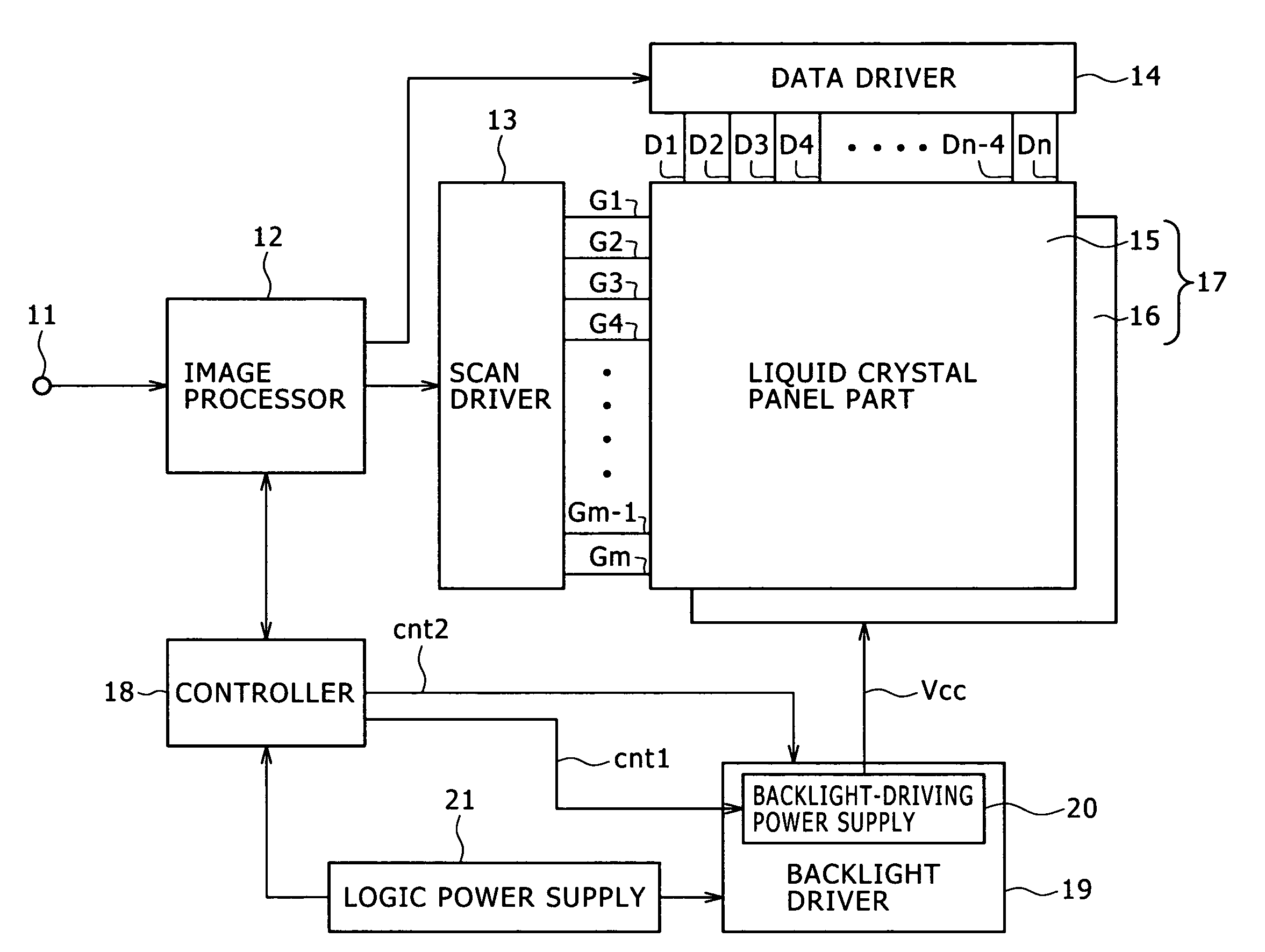
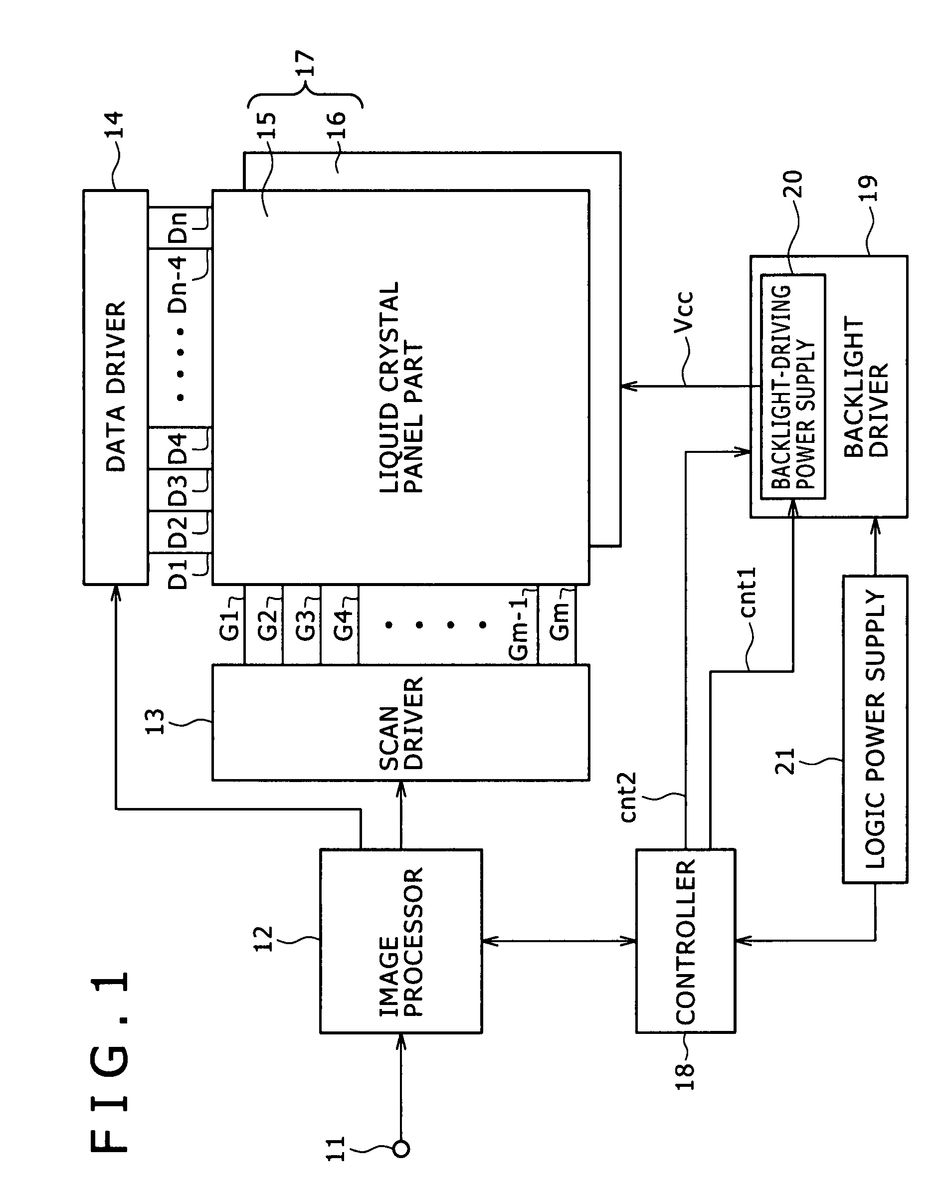
[0025]FIG. 1 is a block diagram showing an entire configuration example of the liquid crystal display of the present embodiment.

[0026]In this display, an image signal (video signal) as the source of an image to be displayed is input as e.g. a digital signal format signal from an input terminal 11 to an image processor 12. For the input image signal, the image processor 12 executes signal processing for various kinds of image quality adjustment, such as processing for conversion into a signal format adapted to displaying on an actual display panel (liquid crystal panel part) and processing for conversion into a resolution adapted to the numbers of horizontal / vertical pixels on the display panel. Furthermore, based...


PUM

PropertyMeasurementUnit
constant-current response timeaaaaaaaaaa
frequencyaaaaaaaaaa

Abstract

A drive device for a light emitting diode element comprises a light emitting diode element circuit part configured to be formed by connecting at least one light emitting diode element based on a predetermined connection form, a power supply unit configured to generate a direct-current (DC) supply voltage for driving the light emitting diode element of the light emitting diode element circuit part for light emission of the light emitting diode element, and apply the DC supply voltage to the light emitting diode element circuit part, a power-supply application on / off unit configured to be provided to turn on / off application of the DC supply voltage to the light emitting diode element circuit part, and a current control circuit part configured to be caused to switch its operation so as to carry out constant current operation if application of the DC supply voltage is in an on-state and carry out voltage keeping operation if application of the DC supply voltage is in an off-state.

Description

CROSS-REFERENCE TO RELATED APPLICATIONS[0001]This application claims priority from Japanese Patent Application No. JP 2006-153791 filed in the Japanese Patent Office on Jun. 1, 2006, the entire content of which is incorporated herein by reference.BACKGROUND OF THE INVENTION[0002]1. Field of the Invention[0003]The present invention relates to a drive device for driving light emitting diode elements, a light source device including such a drive circuit for light emitting diode elements, and a display including such a light source device.[0004]2. Description of the Related Art[0005]As a display, a liquid crystal display that employs a liquid crystal panel is widely prevalent. As is well known, the liquid crystal panel is not a self-luminous panel but displays images through modulation of white light emitted from a light source device referred to as a so-called backlight based on a video signal.[0006]Currently, a cold cathode fluorescent lamp is widely employed as the light source of th...

Claims


Application Information

Patent Timeline
Patent Type & Authority Patents(United States)
IPC IPC(8): G09G3/22G02F1/133G09G3/14G09G3/20G09G3/34G09G3/36H01L33/00
CPCG09G3/3426H05B33/0803H05B33/0827H05B33/0851G09G3/3413G09G2310/061G09G2320/064G09G2330/02G09G2330/021H05B45/10H05B45/325H05B45/37H05B45/395H05B45/46Y02B20/30H05B45/00
Inventor OKABE, MITSURU
Owner SATURN LICENSING LLC
Learn More