Terminal module assembly for molded case circuit breaker and molded case circuit breaker having the same

a terminal module and circuit breaker technology, applied in the direction of circuit breaker switches, switch terminals/connections, protective switch terminals/connections, etc., can solve the problems of inconvenient for both manufacturers and users, difficult to separate fabricate, package and sell the terminal module, and long tim

Inactive Publication Date: 2009-02-24
LG IND SYST CO LTD
View PDF10 Cites 12 Cited by
  • Summary
  • Abstract
  • Description
  • Claims
  • Application Information

AI Technical Summary

Benefits of technology

[0013]Therefore, in order to solve the drawbacks of the related art, an aspect of the present invention is to provide a terminal module assembly of a molded case circuit breaker capable of allowing manufacturers to fabricate, package and sell a terminal module and also allowing users to easily replace only the terminal module with his desired type, by constructing the terminal module as a 3-phases monolithic assembly for a power source side or a load side of the molded case circuit breaker.

Problems solved by technology

Manufacturers of molded case circuit breakers manufacture the related art terminals monolithically with the molded case circuit breaker, without separately providing only the terminals.
However, in case of a typical 3-phases Alternating Current molded case circuit breaker, when assembling each of 6 terminal modules (i.e., 3 terminal modules respectively at the load side and the power source side) to the molded case circuit breaker using screws, it takes long time and it is inconvenient for both of manufacturer and user.
Accordingly, it is difficult to separately fabricate, package and sell the terminal module.
Also, the user may be in trouble for assembling the small component to the molded case circuit breaker.

Method used


Image

  • Terminal module assembly for molded case circuit breaker and molded case circuit breaker having the same
  • Terminal module assembly for molded case circuit breaker and molded case circuit breaker having the same
  • Terminal module assembly for molded case circuit breaker and molded case circuit breaker having the same

Examples


Embodiment Construction

[0038]Description will now be given in detail of the present invention, with reference to the accompanying drawings.

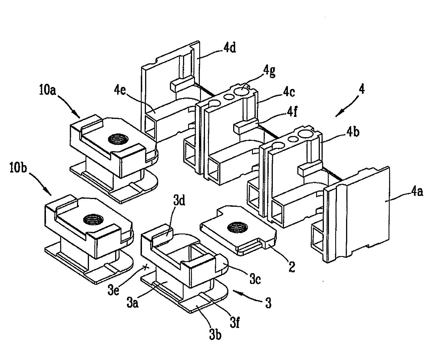
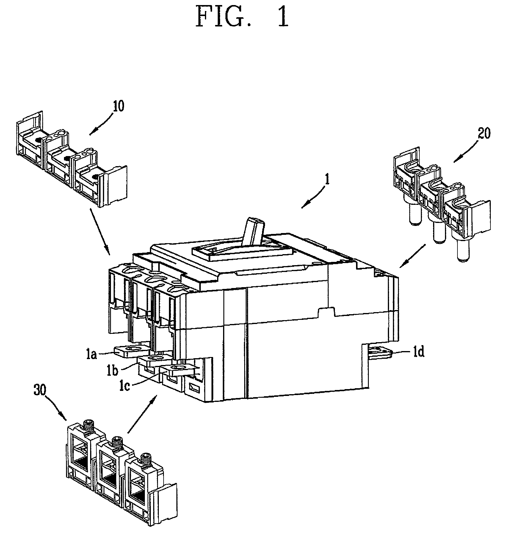
[0039]FIG. 1 illustrates that a terminal module assembly for a molded case circuit breaker is selectively installable to the molded case circuit breaker. As illustrated in FIG. 1, end portions 1a to 1d of 3-phase (i.e., R, S and T) of fixed contactors of a molded case circuit breaker 1 are protruded to the outside of the molded case circuit breaker 1.

[0040]Assuming that the end portions 1a to 1c of the fixed contactors of the three end portions in FIG. 1 are end portions for connecting power source side wires, FIG. 1 shows only the end portion 1d for connecting a load side wire.

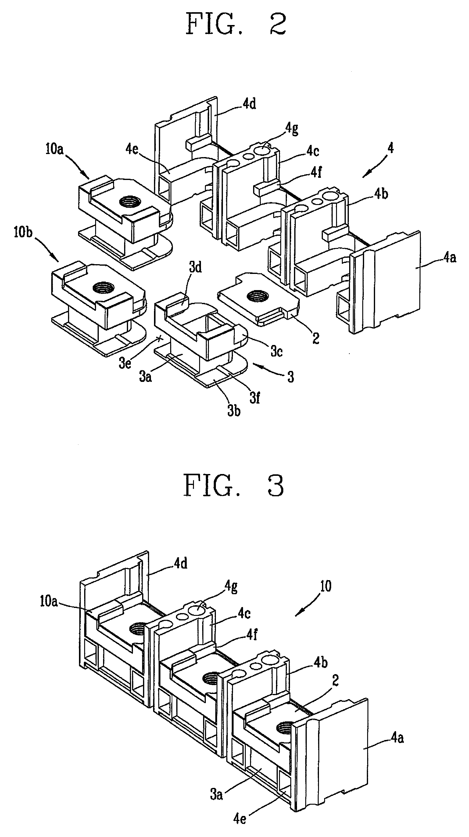
[0041]It can be seen in FIG. 1 that a standard type terminal module assembly 10, a plug-in type terminal module assembly 20 and a box type terminal module assembly 30, in each of which three phases are monolithically assembled, can respectively simply be mounted at the three end portions 1a to 1...


PUM


Abstract

In a terminal of a standard, plug-in or box type molded case circuit breaker, a terminal module assembly for a molded case circuit breaker capable of being removable by easily selecting the terminal type, and a molded case circuit breaker having the terminal module assembly, the terminal module assembly comprising a plurality of terminals provided to selectively have a standard, plug-in or box type and electrically connected to fixed contactors, a plurality of terminal bases provided as many as the number of the terminals and selectively having the standard, plug-in or box type, thus to fixedly support each of the terminals, wherein each terminal is assembled to each terminal base to obtain a terminal module intermediate assembly, and a common supporting base for supporting all of the plurality of intermediate assemblies regardless of the terminal type or terminal base type, wherein the terminal module assemblies having the construction can be attached / detached to / from the molded case circuit breaker.

Description

RELATED APPLICATION[0001]The present disclosure relates to a subject matter contained in priority Korean Application No. 10-2006-0139131, filed on Dec. 29, 2006, which is herein expressly incorporated by reference in its entirety.BACKGROUND OF THE INVENTION[0002]1. Field of the Invention[0003]The present invention relates to a molded case circuit breaker, and particularly, to a terminal module assembly for a molded case circuit breaker in which a terminal part of the molded case circuit breaker is constructed as a module assembly to allow a fast replacement of a terminal module, so that a type of terminal (e.g., a standard type, a plug-in type or a box type) can be fast changed.[0004]2. Background of the Invention[0005]In general, a molded case circuit breaker is an electrical device for protecting circuit and electrical loads by automatically breaking the electrical circuit upon occurring a fault current, such as over-current, ground fault current or short-circuit current, on the e...

Claims


Application Information

Patent Timeline
Patent Type & Authority Patents(United States)
IPC IPC(8): H01H71/08H01H73/20
CPCH01H71/08H01H2011/0037H01H9/08H01R4/36H01H9/02H01H71/00H01H71/02H01H71/10
Inventor OH, KI-HWAN
Owner LG IND SYST CO LTD
Why Eureka
Try Eureka