Ripple filter circuit

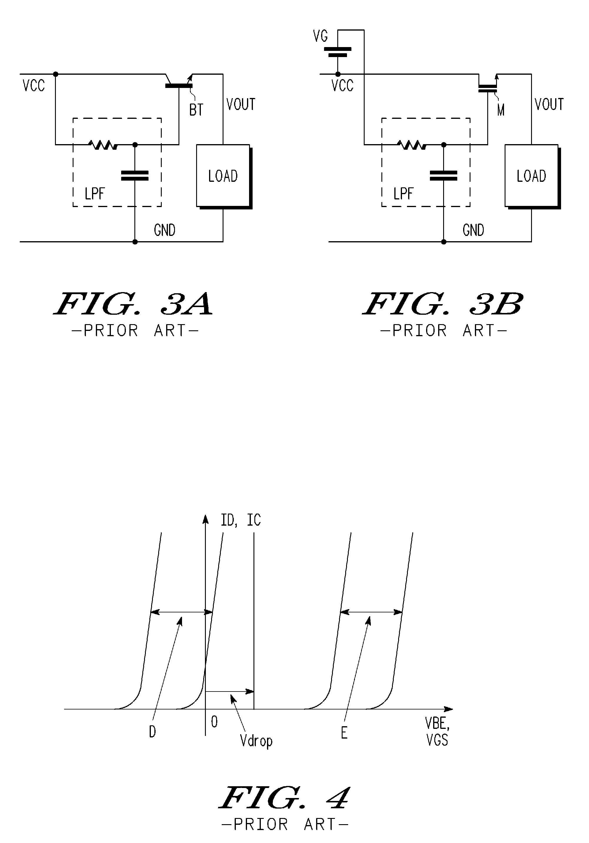
a filter circuit and filter circuit technology, applied in the direction of overvoltage protection resistors, emergency protective arrangements for limiting excess voltage/current, arrangements responsive to excess voltage, etc., can solve the problem of small operating voltage margin, drop voltage vdrop cannot be greatly changed, etc., to achieve the effect of efficient elimination of rippl

Inactive Publication Date: 2009-02-24
NXP USA INC
View PDF5 Cites 7 Cited by
  • Summary
  • Abstract
  • Description
  • Claims
  • Application Information

AI Technical Summary

Benefits of technology

[0010]It is an object of the present invention to provide a ripple filter circuit that efficiently eliminates ripple and ensures that a driving subject is driven even when the operational voltage margin is small.
[0011]One aspect of the present invention is a ripple filter circuit for eliminating ripple. The ripple filter circuit includes a driving transistor, connected to a power supply line, for supplying output voltage to a driving subject connected to a ground line. A reference transistor and a dummy load are connected in series between the power supply line and the ground line. The reference transistor functions as a replica of the driving transistor, and the dummy load corresponds to load of the driving subject. A compensation circuit, connected to a gate terminal of the reference transistor, cancels a characteristic variation in the reference transistor. The compensation circuit provides its output to a gate terminal of the drive transistor via a lowpass filter.

Problems solved by technology

Thus, the drop voltage Vdrop cannot be greatly changed.
Thus, it becomes difficult to ensure the operation of a driving subject having a small operational voltage margin.

Method used


Image

  • Ripple filter circuit
  • Ripple filter circuit
  • Ripple filter circuit

Examples


Embodiment Construction

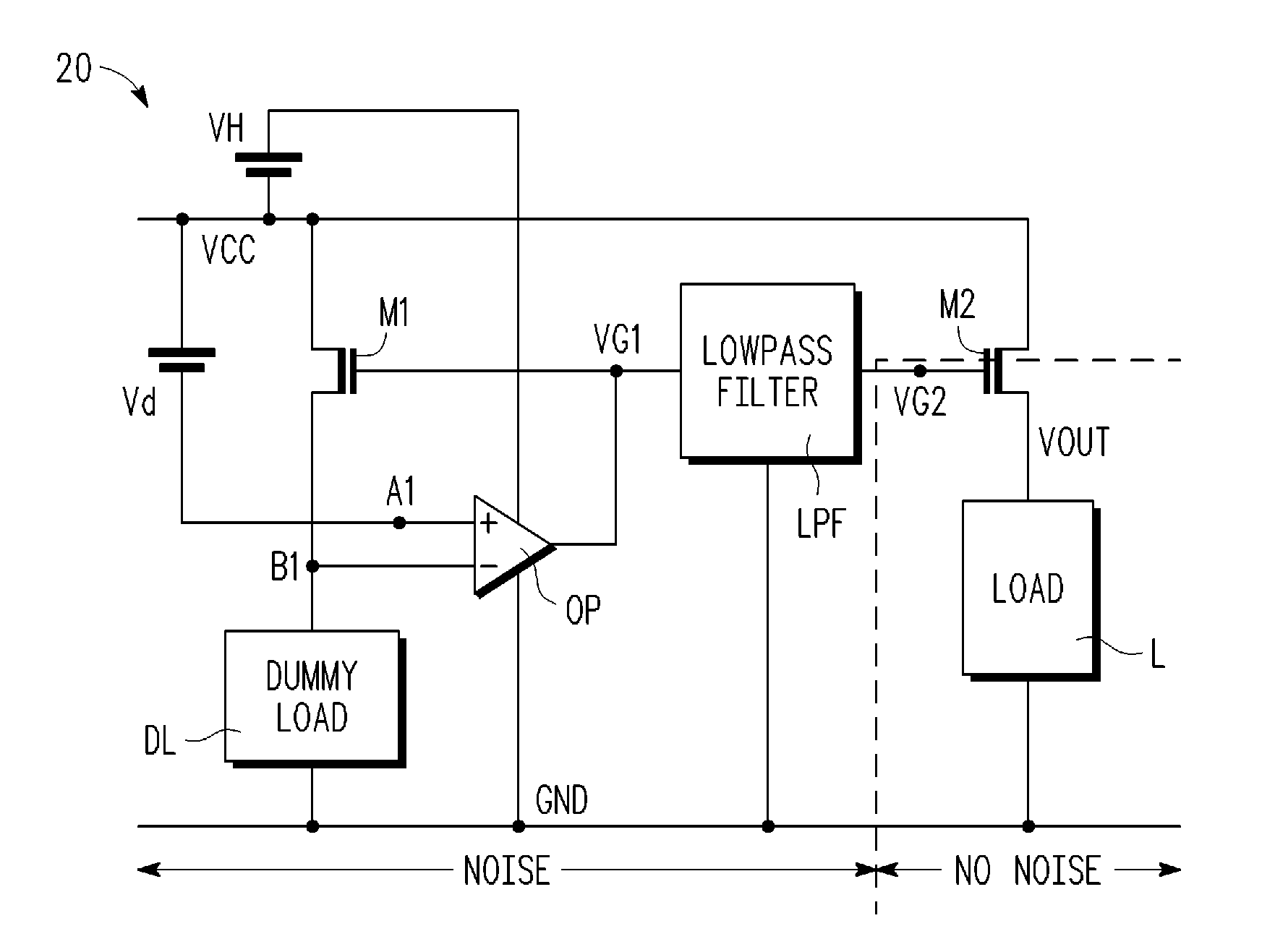
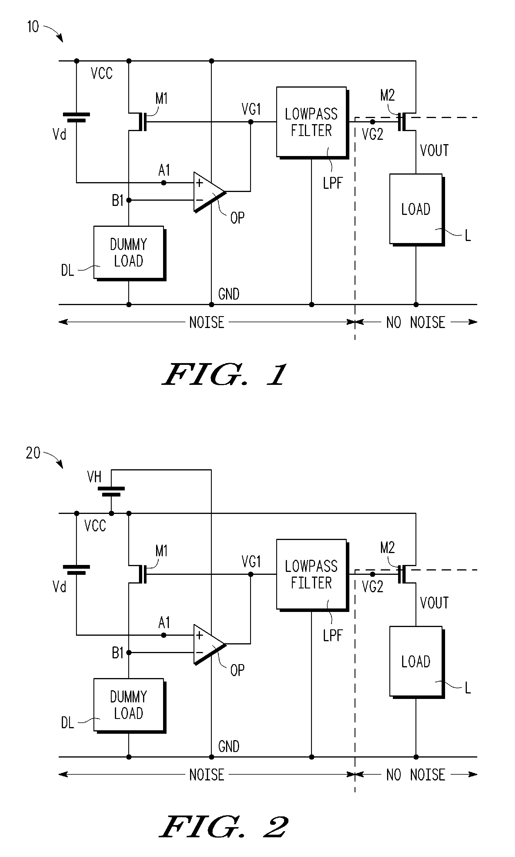
[0019]A first embodiment of the present invention will now be described with reference to FIG. 1. A depression type MOS transistor is used in the first embodiment.

[0020]As shown in FIG. 1, a transistor M2 is connected to a power supply voltage VCC line of a ripple filter circuit 10. The transistor M2 functions as a driving transistor for controlling the supply of power. In the present embodiment, an N-channel depression type MOS transistor is used as the transistor M2. The voltage at the output terminal of the transistor M2 functions as the output voltage VOUT. A load L of a driving subject is connected between the transistor M2 and ground GND.

[0021]A transistor M1, which functions as a reference transistor, and a dummy load DL are connected in series between the power supply voltage VCC line and ground GND line. The transistor M1 and the dummy load DL function as replicas of the transistor M2 and the load L. The transistor M1, which is smaller in size than the transistor M2, is for...


PUM


Abstract

A ripple filter circuit for ensuring the driving of a driving subject while efficiently eliminating ripple even when the operational voltage margin is small. A first transistor, which is connected to a power supply voltage line, is connected to a ground line via a load of the driving subject. A second transistor, which has substantially the same characteristics as the first transistor, and a dummy load are arranged between the power supply voltage line and the ground line. An operational amplifier includes an inverting input terminal, connected between the second transistor and the dummy load, and a non-inverting terminal at which the voltage is decreased by a predetermined voltage from the power supply voltage. The operational amplifier also includes an output connected to the gate terminal of the second transistor and to the gate terminal of the first transistor via a lowpass filter.

Description

BACKGROUND OF THE ART[0001]The present invention relates to a ripple filter circuit for eliminating ripple from, for example, a power supply circuit.[0002]A ripple circuit known in the prior art functions to eliminate ripple (refer to, for example, Japanese Laid-Open Patent Publication No. 8-317633, FIG. 2). The structure of a ripple filter circuit will now be described with reference to FIG. 3A. A bipolar transistor BT is arranged in a power supply voltage VCC line. The bipolar transistor BT forms a ripple filter circuit, which is grounded via a load L functioning as a driving subject. A lowpass filter LPF is connected to the base terminal of the bipolar transistor BT. The lowpass filter LPF includes a resistor and a capacitor. Power is supplied from the power supply voltage VCC line to the base terminal of the bipolar transistor BT via the resistor. Further, the base terminal is connected to a ground GND line via the capacitor.[0003]As long as the base voltage at the bipolar trans...

Claims


Application Information

Patent Timeline
Patent Type & Authority Patents(United States)
IPC IPC(8): H02M1/14
CPCH02M1/15
Inventor KIMURA, HIROYUKI
Owner NXP USA INC
Why Eureka
Try Eureka