Devices, systems, and methods for controlling a shutter

a technology of shutters and devices, applied in the field of devices, systems, and methods for controlling shutters, can solve the problems of complex software, add to the size and cost of the optical or imaging system,

Active Publication Date: 2009-02-24
MEMSIC
View PDF12 Cites 3 Cited by
  • Summary
  • Abstract
  • Description
  • Claims
  • Application Information

AI Technical Summary

Benefits of technology

[0011]Using frequency data from the acceleration waveform data, the controller can predict a time between peak accelerations. As a result, the controller can open and close the shutter at an optimal time for controlling blurring, i.e., at a time corresponding to the predicted time between peak accelerations as measured from a real-time acceleration amplitude maximum.

Problems solved by technology

These systems, however, require extensive memory and complex software, which add to the size and cost of the optical or imaging system.

Method used


Image

  • Devices, systems, and methods for controlling a shutter
  • Devices, systems, and methods for controlling a shutter
  • Devices, systems, and methods for controlling a shutter

Examples


Embodiment Construction

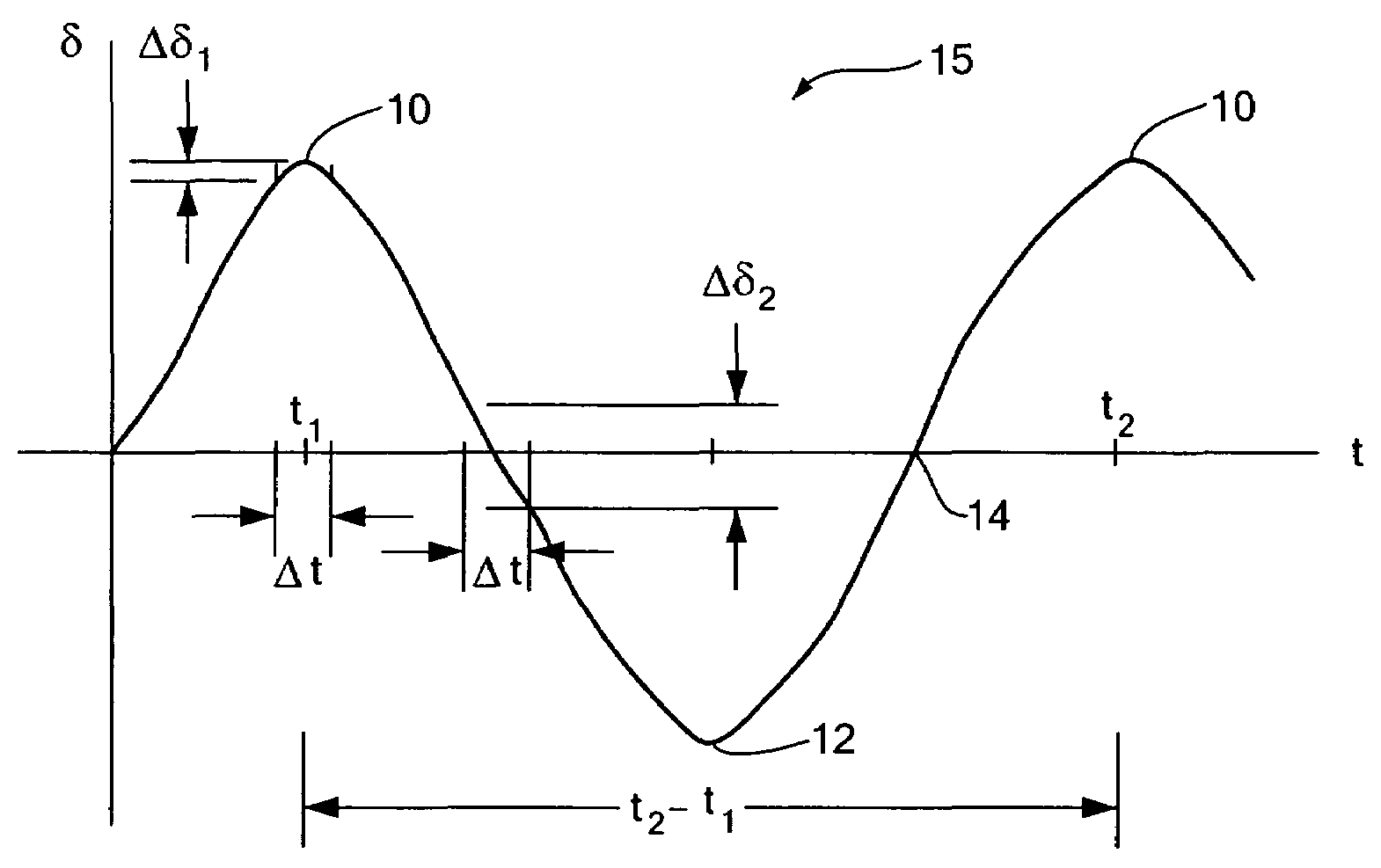
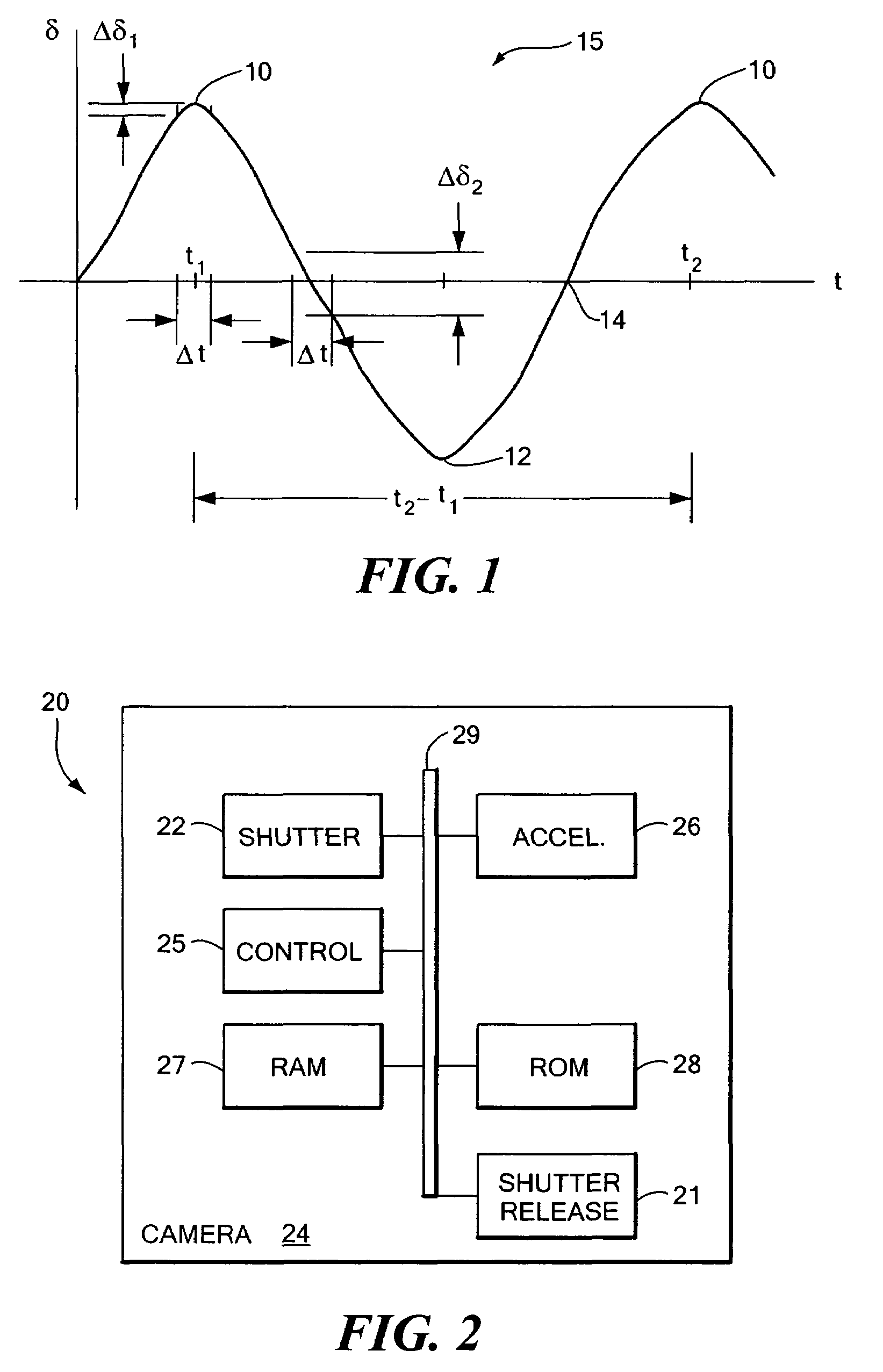
[0017]Disclosed is a shutter control device for an optical system or an imaging system that improves image sharpness by reducing blurring resulting from vibrations, e.g., hand vibrations. Referring to FIG. 1, as a rule, vibrations, i.e., displacement (δ) over time (t), are sinusoidal in all three-dimensions. At and near the peaks 10 and troughs 12 of the sinusoidal waveform 15, the slope of the sinusoidal waveform 15, i.e., the change in displacement with respect to a very short period of time (Δδ1 / Δt), is substantially zero. In contrast, at or near a point of zero displacement 14, i.e., where δ=0, the change in displacement with respect to the same short period of time (Δδ2 / Δt) is more significant. Accordingly, very near or at the peaks 10 or troughs 12 of the vibration sinusoid 15 there is substantially no relative-movement due to vibrations, whereas near the points of zero displacement, vibrations are at a maximum.

[0018]Referring to FIG. 2, a system 20 for controlling the instant...


PUM


Abstract

Devices, systems, and methods for controlling a shutter of a still or video camera or cellular telephone, to reduce blurring due to motion of vibrations are disclosed. The control device includes an inertial sensor for measuring acceleration, velocity and / or angular rotation and for providing data therefrom and a controller for calculating an acceleration amplitude and frequency for predicting the time between acceleration maximums. The controller opens and closes the camera shutter at a time corresponding to the predicted time between maximum accelerations as measured from a real-time acceleration maximum, negating the need for post-imaging correction.

Description

CROSS REFERENCE TO RELATED APPLICATIONS[0001](Not applicable)STATEMENT REGARDING FEDERALLY SPONSORED RESEARCH OR DEVELOPMENT[0002](Not applicable)BACKGROUND OF THE INVENTION[0003]1. Field of the Invention[0004]Devices, systems, and methods for controlling a shutter to reduce blurring due to vibrations are disclosed.[0005]2. Description of the Related Art[0006]Optical and imaging systems such as cameras, video cameras, cell phones, and the like project the image of an object onto a focal plane where, when the shutter of the optical or imaging system is activated, the image is recorded on film or digitally. To improve the sharpness of the recorded image, some form of motion or vibration compensation can be implemented to compensate for any blurring that may result from undesirable movement of the optical or imaging system, e.g., due to vibrations.[0007]Some conventional motion and / or vibration compensation devices involve measuring one or more parameters, e.g., angular velocity, with ...

Claims


Application Information

Patent Timeline
Patent Type & Authority Patents(United States)
IPC IPC(8): G03B17/00
CPCG03B17/00
Inventor ZHAO, YANG
Owner MEMSIC
Why Eureka
Try Eureka