Seam ravel preventing apparatus and ravel preventing method

a technology of preventing equipment and ravels, which is applied in the direction of sewing apparatus, needle severing devices, textiles and paper, etc., can solve the problems of affecting sewing operations, affecting sewing operations, and affecting sewing operations, so as to prevent raveling and perform the operation stably , the effect of preventing raveling

Inactive Publication Date: 2009-03-03
YAMATO SEWING MASCH MFG CO LTD
View PDF16 Cites 15 Cited by
  • Summary
  • Abstract
  • Description
  • Claims
  • Application Information

AI Technical Summary

Benefits of technology

[0014]In the first aspect, with the time at which the looper is in the advance state just before the end of sewing as the starting point, the looper thread hanging hook provided on the right rear side of the needle drop position is forced to perform the advance and retreat operation to catch the looper thread near the left advance end of the looper with the advance in the left forward direction and hold the caught looper thread on the rear side of the needle drop position with the retreat to the right rear side. Next, sewing is performed for at least one stitch in this state, the thread cutting hook provided on the right side of the needle drop position is forced to perform the advance and retreat operation so that the thread cutting hook is inserted into the loops of the needle threads where the looper is passed with the advance in the left direction, the looper thread is caught near the left advance end of the looper by the first hook section provided at the tip of the thread cutting hook and the looper thread held by the looper thread hanging hook is caught together with the needle threads by the second hook section provided in the middle of the thread cutting hook with the subsequent retreat to the right direction, and the looper thread and needle threads are cut with the thread cutting knife that successively comes into slide-contact with the second and first hook sections with the further retreat of the thread cutting hook, thereby realizing a ravel preventing state.
[0029]Further, in the seam ravel preventing apparatus according to the fifth aspect, since the looper thread hanging hook advances and retreats to cross obliquely the tip of the looper located on the left advance end, it is possible certainly catch and hold the looper thread with the looper thread hanging hook, and thus the present invention has advantages effects, such as making it possible to stably perform the operation of preventing raveling.

Problems solved by technology

However, in order to mount the looper thread hanging hook including a driving mechanism for advancing and retreating the looper thread handing hook, a large space is required on the rear side of the needle drop position that is set in the end portion of the sewing bed, and thus there is a problem that it is difficult to apply this structure to a sewing machine that comprises a small-diameter cylindrical bed to handle a cylindrical sewn product.
In this structure, however, since a swing axis of the looper thread hanging hook and a driving mechanism for the swing axis need to be placed on the rear left side of the needle drop position, the end portion of the bed becomes larger in diameter and longer to ensure the mount space therefor and may interfere with a sewing operation.

Method used


Image

  • Seam ravel preventing apparatus and ravel preventing method
  • Seam ravel preventing apparatus and ravel preventing method
  • Seam ravel preventing apparatus and ravel preventing method

Examples


Embodiment Construction

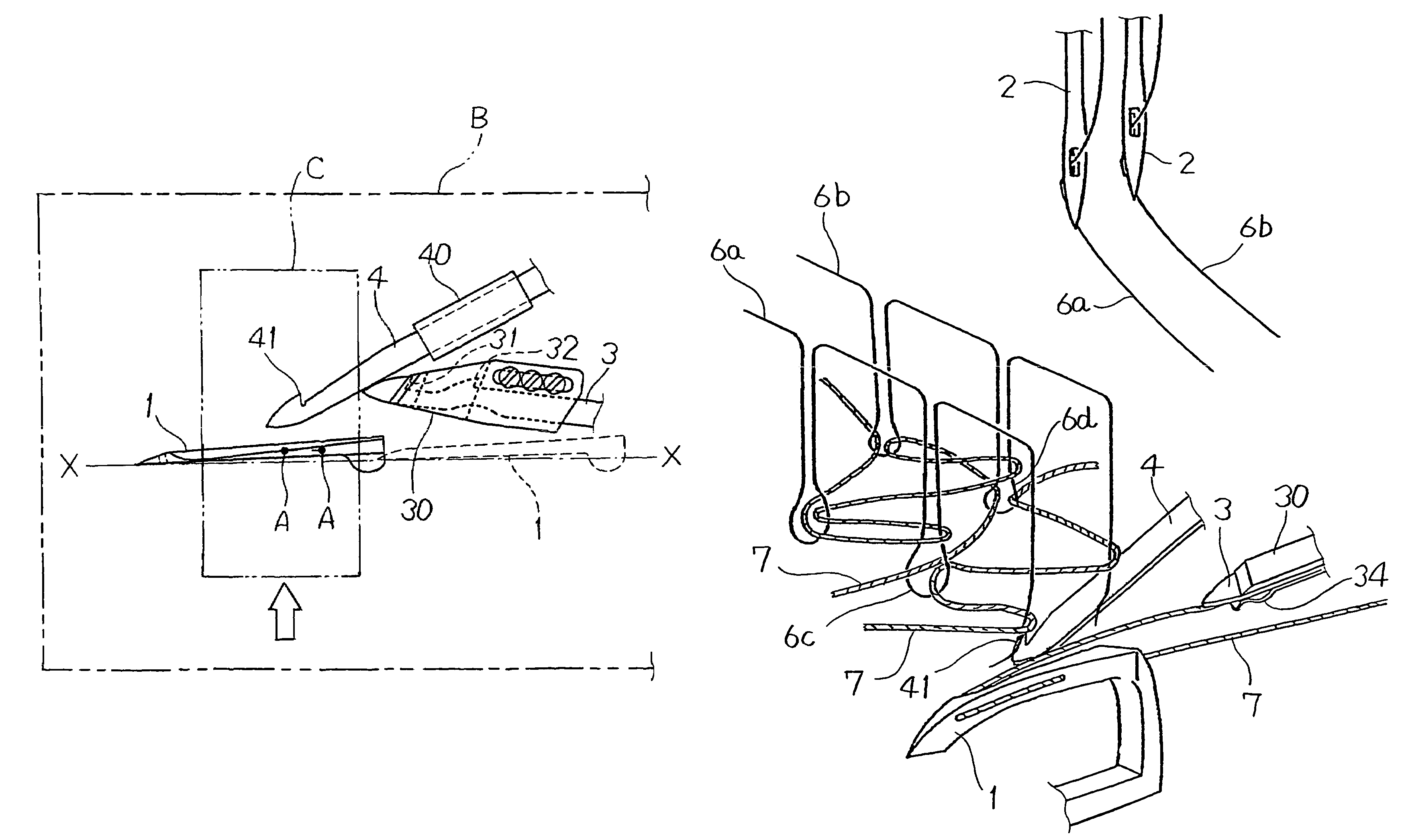
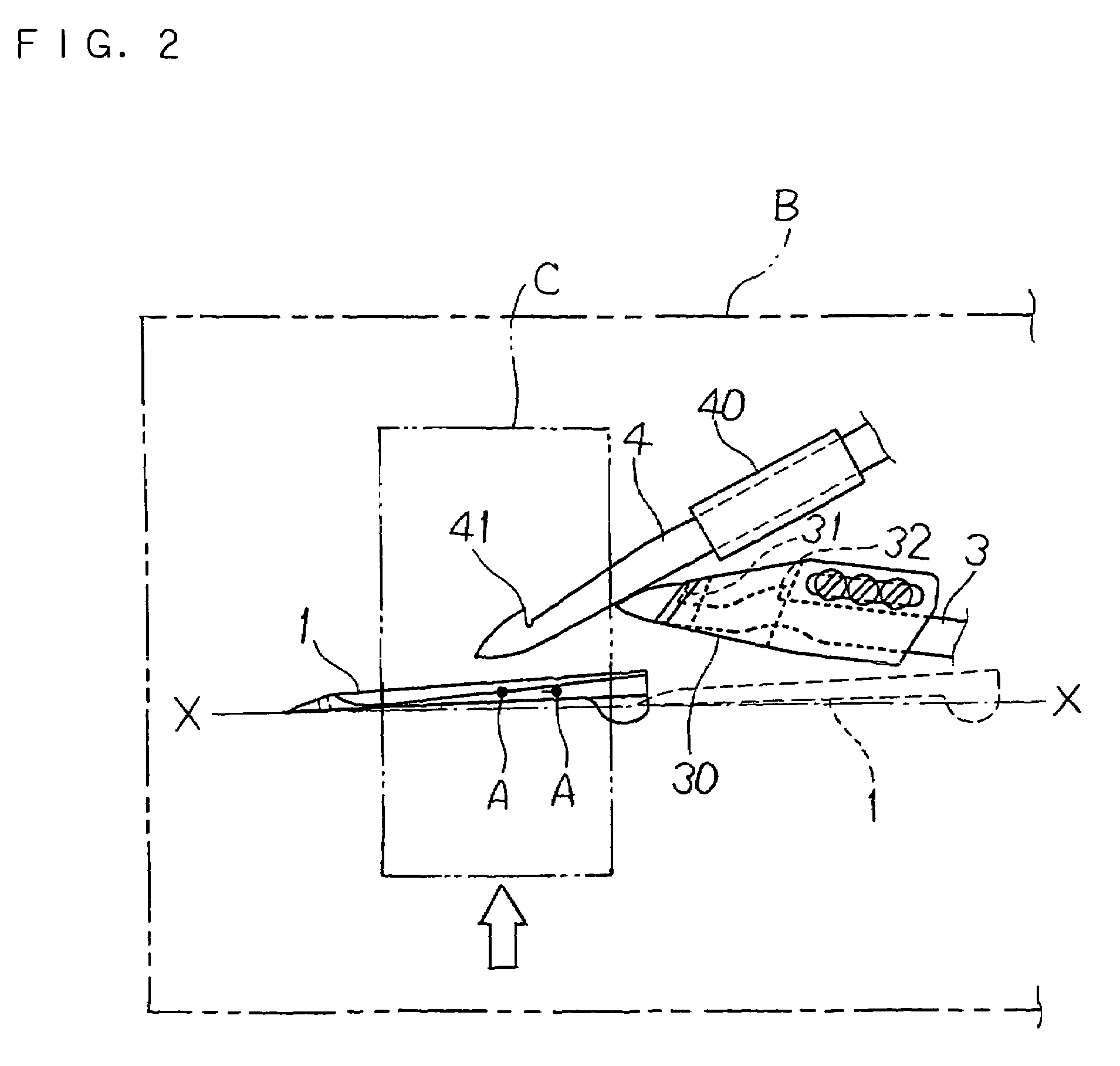
[0045]The following description will explain in detail the present invention, based on the drawings illustrating an embodiment thereof. FIGS. 2 to 5 are plan views showing schematically the structures of essential parts of a seam ravel preventing apparatus according to the present invention (hereinafter referred to as the apparatus of the present invention). Note that the terms “left” and “right” used in the explanation represent the left and right of FIGS. 2 to 6 and the end portion of the sewing bed is the left side.

[0046]The apparatus of the present invention is provided in a sewing machine for sewn cloth (not shown) that is fed forward or backward (the direction shown by an open arrow in FIG. 2) with two needles 2 and 2 that move down to separate needle drop positions indicated by A and A, respectively, in FIGS. 2 to 5 (see FIGS. 9 to 13), and a looper 1 that performs an advance and retreat operation including these needle drop positions A and A in the middle thereof. In FIGS. 2...


PUM


Abstract

A looper is brought into an advance state at the end of sewing, and a looper thread hanging hook arranged on the right rear side of a needle drop position is forced to advance and retreat to catch a looper thread running to the rear side of the looper and hold it on the rear side of the needle drop position. After performing sewing for one stitch in this state, the thread cutting hook arranged on the right side of the needle drop position is forced to advance and retreat to catch the looper thread running to the rear side of the looper with a first hold section and catch needle threads and the looper thread held by the looper thread hanging hook with a second hook section, and then these threads are collectively cut by bringing them into slide-contact with a thread cutting knife.

Description

CROSS-REFERENCE TO RELATED APPLICATIONS[0001]This non-provisional application claims priority under 35 U.S.C. §119(a) on Patent Application No. 2005-117532 filed in Japan on Apr. 14, 2005 and Patent Application No. 2005-244854 filed in Japan on Aug. 25, 2005, the entire contents of which are hereby incorporated by reference.BACKGROUND OF THE INVENTION[0002]1. Field of the Invention[0003]The present invention relates to an apparatus that is provided in a sewing machine for performing sewing using a looper thread and needle threads, such as a multi-thread chain stitch sewing machine and a covering chain stitch sewing machine, to prevent raveling of a seam at the end of sewing, and also relates to a ravel preventing method implemented using this apparatus.[0004]2. Description of Related Art[0005]In a multi-thread chain stitch sewing machine and a covering chain stitch sewing machine, loops of needle threads 6a and 6b and a looper thread 7 are intertwined in an inter-looping manner on t...

Claims


Application Information

Patent Timeline
Patent Type & Authority Patents(United States)
IPC IPC(8): D05B65/00D05B57/00
CPCD05B65/02D05B1/10D05B57/06D05B57/34
Inventor TANAKA, YOSHIYUKIYOKOYAMA, RYUICHIYASUZAWA, OSAMU
Owner YAMATO SEWING MASCH MFG CO LTD
Why Eureka
Try Eureka