Power steering system for vehicle

a technology for steering systems and vehicles, applied in the direction of power steering, electrical steering, transportation and packaging, etc., can solve the problems of increasing the number of components, and achieve the effect of reducing the number of components

Inactive Publication Date: 2009-03-03
HONDA MOTOR CO LTD
View PDF11 Cites 36 Cited by
  • Summary
  • Abstract
  • Description
  • Claims
  • Application Information

AI Technical Summary

Benefits of technology

[0007]The present invention has been made in consideration of the above-mentioned circumstances. Accordingly, it is an object of the present invention to provide a power steering system for a vehicle, which enables a reduction in the number of component parts and realization of a compact design.
[0014]According to the first aspect of the present invention, the steering shaft is rotatably suppoted on only the single support case mounted to the cross member, and at least the electric motor of the power assist unit is mounted to the cross member through the support shaft. Therefore, the supporting of the steering shaft and the mounting of the power assist unit to the cross member are performed with the single support case, so that the steering shaft and the power assist unit can be supported on the cross member on the vehicle body side while using a compact configuration having a reduced number of component parts.
[0017]According to the fourth aspect of the present invention, it is possible to regulate the relative positions of the support case for rotatably bearing the steering shaft thereon and the bracket, and the inclination of the axis of the steering shaft can be easily regulated.
[0018]According to the fifth aspect of the present invention, the problem that a portion protruding to the passengers' side is generated due to the layout of the electric motor can be obviated, and it is easy to secure the space for the passengers.
[0019]According to the sixth aspect of the present invention, it is possible to prevent the harness connected to the torque sensor from protruding to the front side, thereby to simplify the support case mounting structure, and to facilitate connection of the harness.

Problems solved by technology

This leads to an increase in the number of component parts.

Method used


Image

  • Power steering system for vehicle
  • Power steering system for vehicle
  • Power steering system for vehicle

Examples


Embodiment Construction

[0033]The present invention will now be described with reference to the accompanying drawings, wherein the same or similar elements will be identified with the same reference numera.

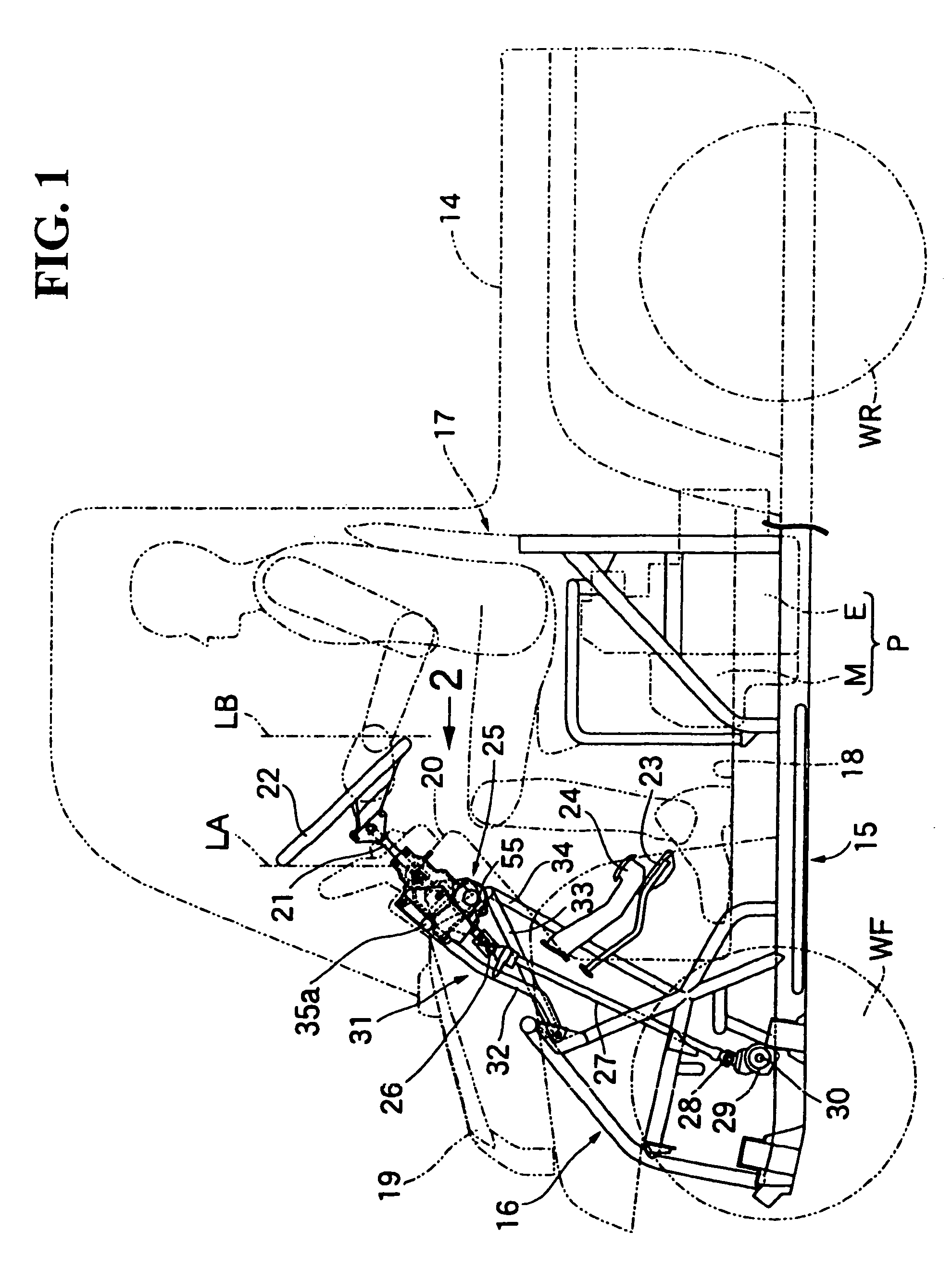
[0034]FIGS. 1 to 11 illustrate one embodiment of the present invention. First, in FIG. 1, the vehicle is a four-wheel, low-floor, small-type vehicle used as a carrying all-terrain vehicle such as a golf cart. Left and right front wheels WF are used as steering wheels and are suspended at front portions of a vehicle body 15. Left and right rear wheels WR are used as driving wheels and are suspended at rear portions of the vehicle body 15. The vehicle body 15 has a support frame 16 at its front end formed by combining a plurality of pipes. A dashboard 20 is disposed in continuation with a rear portion of a front cover 19 covering the support frame 16.

[0035]A low-floor type floor portion 18 on which the feet of the passengers seated on a passengers' seat 17 can be placed is provided on the vehicle body 15 b...


PUM


Abstract

A power steering system for a vehicle includes a power assist unit composed of a unitized combination of a torque sensor, an electric motor and a power transmission mechanism. The power assist unit is mounted to a cross member provided on the vehicle body side, to enable a reduction in the number of component parts and realization of a compact design. A steering shaft is rotatably supported on only a single support case mounted to a cross member. At least an electric motor of a power assist unit is mounted to the cross member through the support case.

Description

CROSS-REFERENCE TO RELATED APPLICATIONS[0001]This nonprovisional application claims priority under 35 U.S.C. §119(a) on Patent Application No. 2005-053078, filed in Japan on Feb. 28, 2005, the entirety of which is incorporated herein by reference.BACKGROUND OF THE INVENTION[0002]1. Field of the Invention[0003]The present invention relates to a power steering system for a vehicle. A power assist unit is composed of a unitized combination of a torque sensor, an electric motor and a power transmission. The torque sensor is for detecting an operational torque exerted on a steering handle. The electric motor has its axis orthogonal to a plane containing the axis of a steering shaft provided in connection with the steering handle and is operated according to a detected value detected by the torque sensor. The power transmission mechanism is for transmitting rotational power of the electric motor to a power transmission shaft for transmitting a steering force to the side of a steering whee...

Claims


Application Information

Patent Timeline
Patent Type & Authority Patents(United States)
IPC IPC(8): B62D5/04
CPCB62D1/16B62D5/04B62D5/0403B62D5/0409B62D25/145B62D33/0617
Inventor KOBAYASHI, TAKESHI
Owner HONDA MOTOR CO LTD
Why Eureka
Try Eureka