

Outer conductor terminal
a technology of outer conductors and terminals, applied in the direction of electrical equipment, connections, connections effected by permanent deformation, etc., can solve the problems of insufficient locking force and coaxial wire lock structur
- Summary
- Abstract
- Description
- Claims
- Application Information
AI Technical Summary
Benefits of technology
Problems solved by technology
Method used
Image

Examples
first embodiment
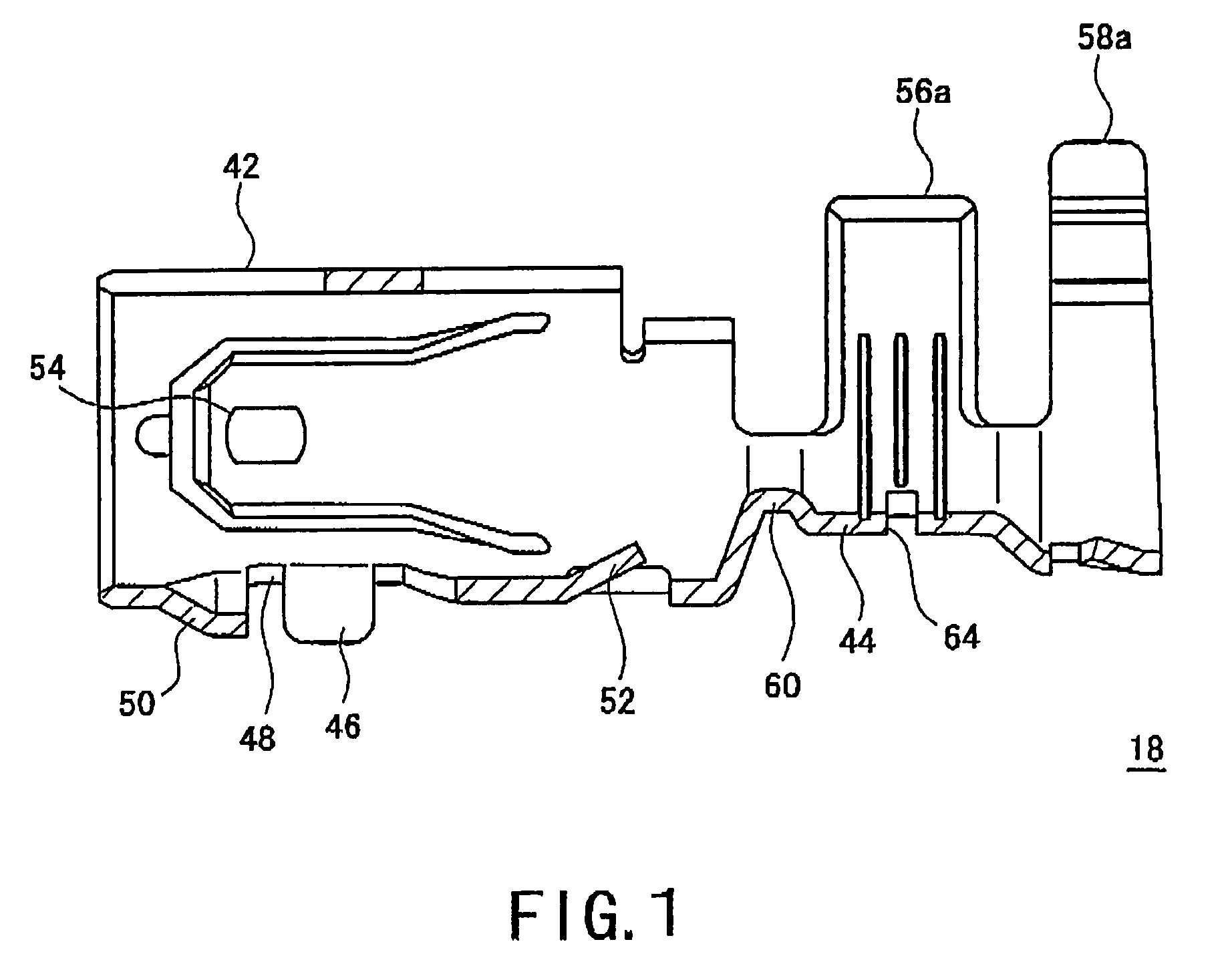
[0033]As shown in FIG. 4, in a coaxial connector 10 having an outer conductor terminal 18 according to the present invention, at an end of a coaxial wire 12, an inner conductor terminal 14 is connected to an inner conductor 20 of the coaxial wire 12, the inner conductor terminal 14 is held by a dielectric 16, the dielectric 16 is incorporated into the outer conductor terminal 18, and the outer conductor terminal 18 is connected to a braid 24 of the coaxial wire 12.
[0034]The coaxial wire 12 has a structure in which the inner conductor 20 which is a stranded wire of elemental wires made of copper and the like, an insulation 22 which covers the inner conductor 20, the braid 24 as an outer conductor which is a braided wire of elemental wires made of copper and the like and covers the insulation 22, and a sheath 26 as an exterior covering which covers the braid 24 are arranged coaxially. Since the inner conductor 20 is covered by the braid 24, an extraneous noise and the like can be elec...
second embodiment
[0044]Next, an outer conductor terminal according to the present invention will be described.
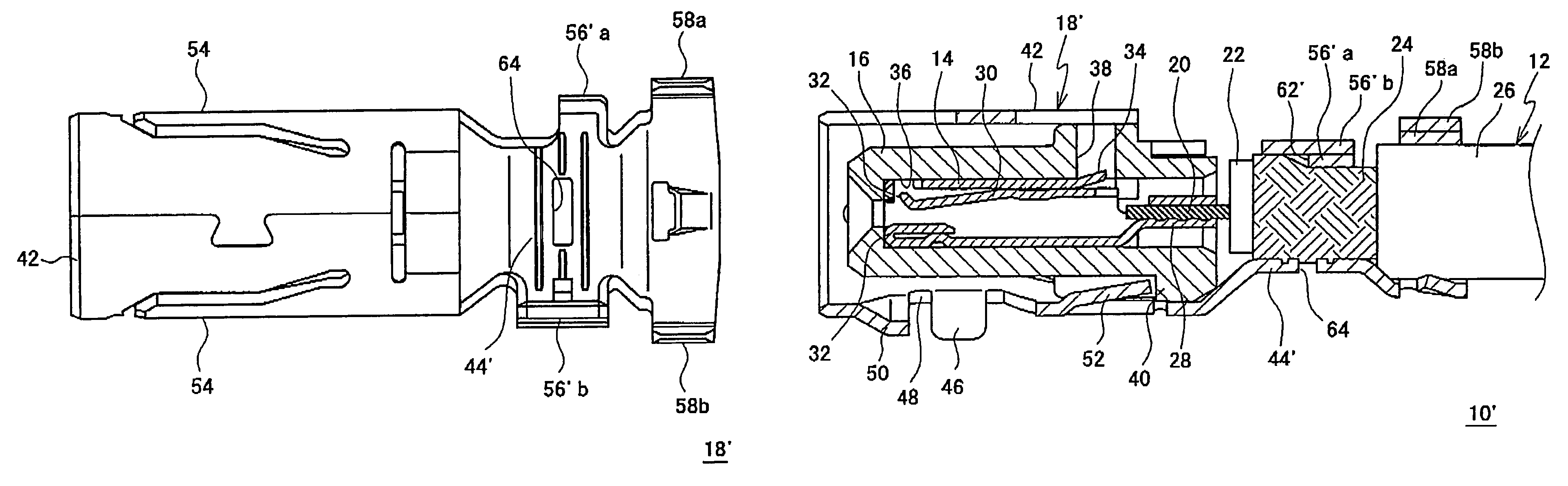
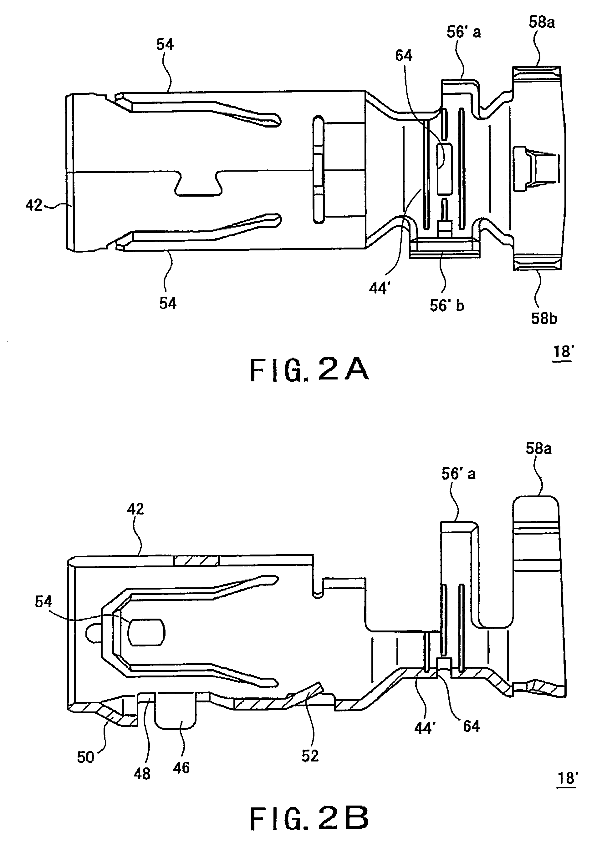
[0045]An outer conductor terminal 18′ according to the second embodiment of the present invention, which has a pair of braid crimping pieces 56′a and 56′b which are made to overlap on the end of the braid 24, has a configuration different from that of the outer conductor terminal 18 according to the first embodiment of the present invention in that the width of the inside braid crimping piece 56′ a in the longitudinal direction is about half the width of the outside braid crimping piece 56′b, and the push-up projection 60 included in the first embodiment is not provided on the lower wall of the crimp section 44 on the terminal top side, as shown in FIGS. 2A and 2B. The other elements that are the same as in the first embodiment are assigned the same reference letters as in the first embodiment, and detailed descriptions thereof are omitted.
[0046]As shown in FIGS. 7A and 7B, generally, braid ...
third embodiment
[0049]Next, an outer conductor terminal according to the present invention will be described.
[0050]An outer conductor terminal 18″ according to the third embodiment of the present invention has, as shown in FIG. 3, the push-up projection 60 which is the characterizing feature of the outer conductor terminal 18 according to the first embodiment as shown in FIG. 1 and the braid crimping pieces 56′a and 56′b of distinctive shape which are the characterizing features of the outer conductor terminal 18′ according to the second embodiment as shown in FIGS. 2A and 2B. To be specific, the push-up projection 60 is formed to project upward on the lower wall of a crimp section 44″ on the terminal top side, and with the braid crimping pieces 56′a and 56′boverlapping on the end of the braid 24, the width of the inside braid crimping piece 56′a is about half the width of the outside braid crimping piece 56′b. The other elements that are the same as in the first embodiment are assigned the same re...
PUM
 Abstract
Description
Claims
Application Information