Directionally controllable, self-stabilizing, rotating flying vehicle

a flying vehicle, self-stabilizing technology, applied in the field of flying vehicles, can solve the problems of difficult implementation of directional control, great effort still made in the prior art to eliminate or counteract the torque created by horizontal rotating propellers, etc., and achieve the effect of reducing the level of drive signals

Inactive Publication Date: 2009-03-03
DAVIS STEVEN
View PDF2 Cites 80 Cited by
  • Summary
  • Abstract
  • Description
  • Claims
  • Application Information

AI Technical Summary

Problems solved by technology

However, a great deal of effort is still made in the prior art to eliminate or counteract the torque created by horizontal rotating propellers in flying aircraft in an effort to increase stability.
However, when a vehicle completely rotates, such as a flying saucer or any other rotating vehicle, the rotating vehicle loses its orientation as soon as it begins to spin, making directional control difficult to implement.

Method used


Image

  • Directionally controllable, self-stabilizing, rotating flying vehicle
  • Directionally controllable, self-stabilizing, rotating flying vehicle
  • Directionally controllable, self-stabilizing, rotating flying vehicle

Examples


first embodiment

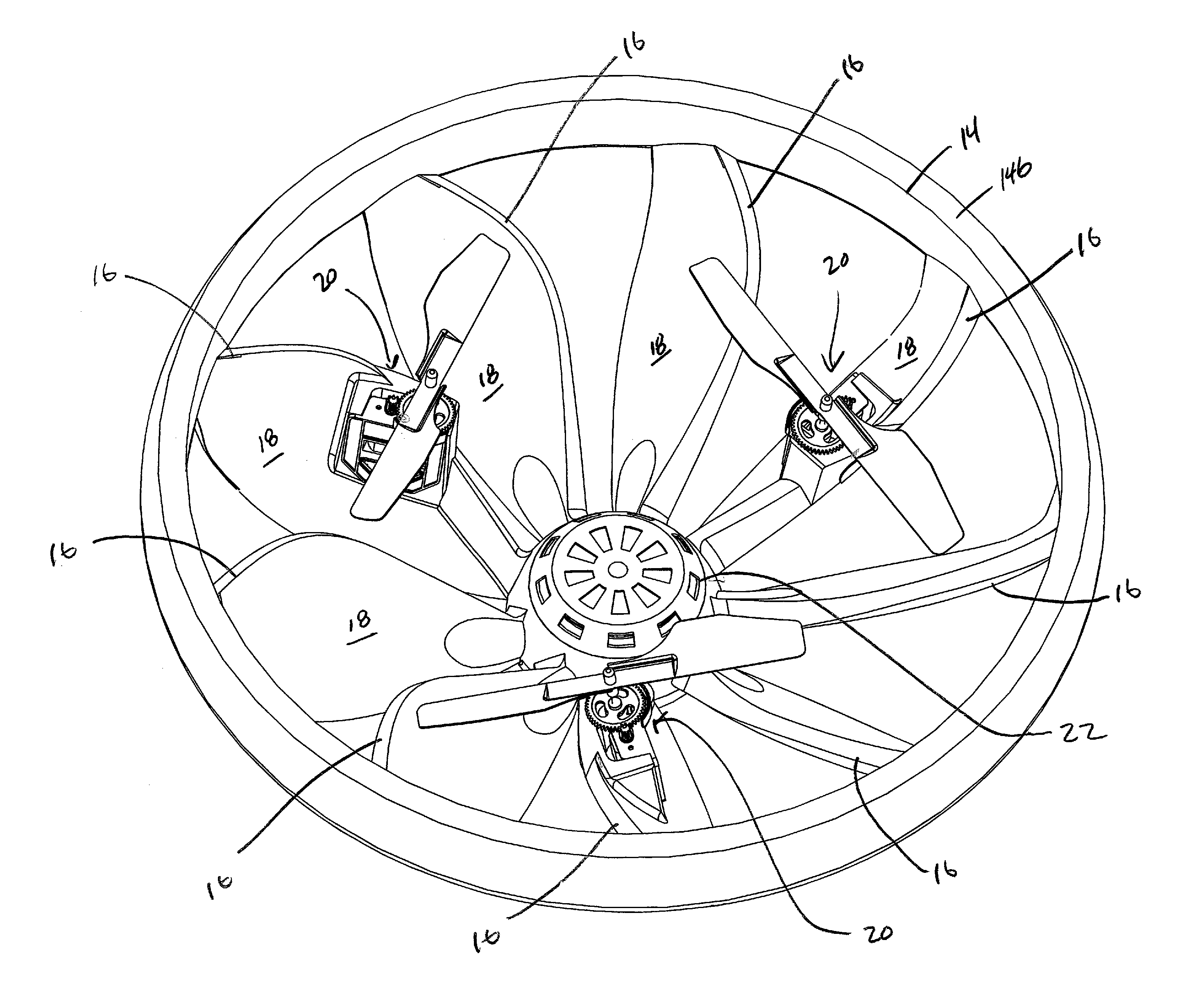
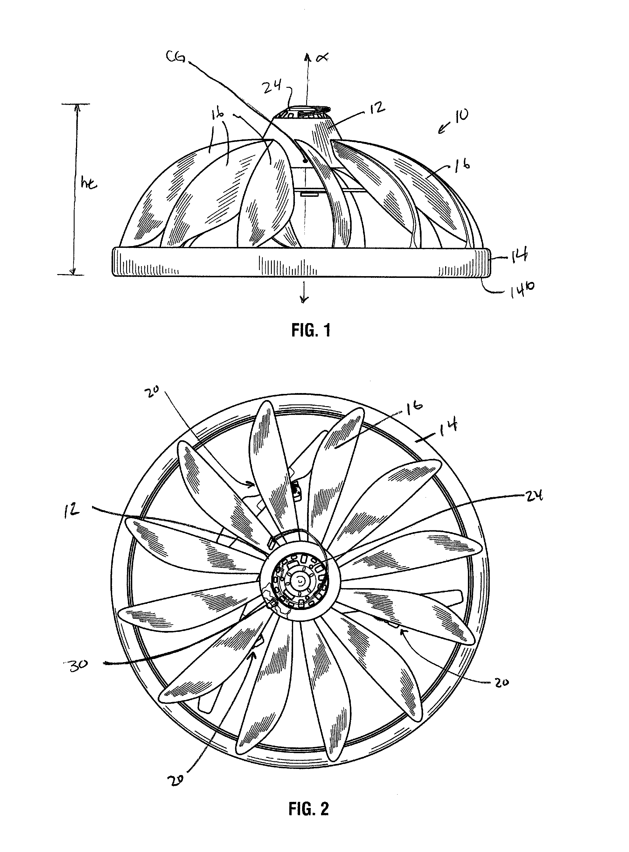
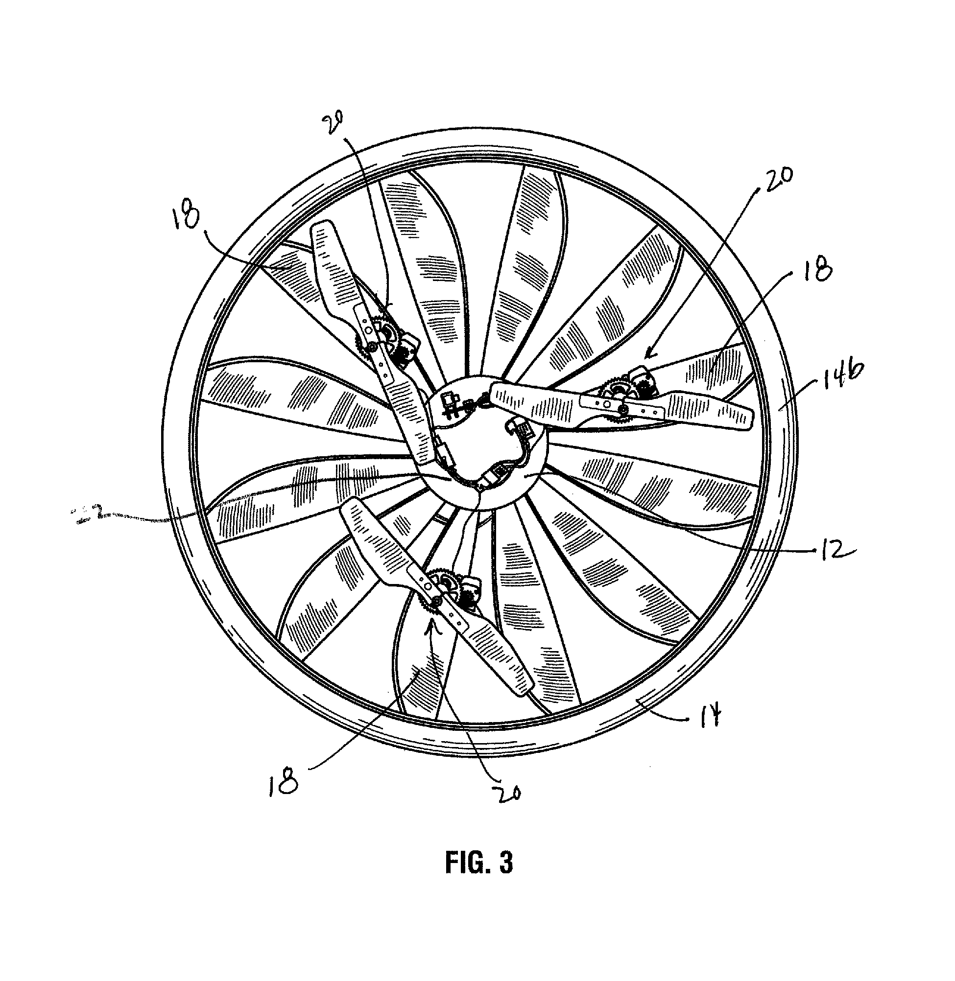
[0035]Referring to FIGS. 1 through 3, in the present invention a flying rotating vehicle 10 is provided. The vehicle 10 includes a hub 12 and an outer ring 14. A plurality of blades 16 extend outwardly and downwardly from the hub 12 to the outer ring 14. Separately secured to the underside 18 of three of the blades 16 are rotor assemblies 20. FIG. 4 illustrates another vehicle 10 that has fewer blades 16, further illustrating that the number of blades would not affect that scope of the invention. The placement of and manner of securing the rotor assemblies 20 to the flying rotating vehicle 10 may also change. For example, the rotor assemblies 20 may be secured to the flying rotating vehicle 10 by any means for securing. Such means may include the method described hereinabove, or may include securing each rotor assembly 20 to one or more rods (not shown) that are positioned below the blades and allow the rotor assemblies to be secured to the flying rotating vehicle 10 at a position b...

embodiment 100

[0053]In a first control system embodiment 100, FIG. 9a, a hand held controller 110 transmits a non directional IR signal through IR emitters 112. The non directional IR signal is also encoded with the control inputs from the operator. The position reference of the rotating vehicle is determined by a directional IR receiver 114 on the vehicle 10. When the directional IR receiver 114 receives the signal from the hand held controller 110, the microprocessor 28 on the rotating vehicle determines that the rotor assembly M1 is positioned at zero degrees. A non directional IR receiver 116 on the rotating vehicle 10 is used to receive and decode the control input commands from the hand held controller. As mentioned above, the control input commands include throttle and directional control commands, received through a throttle control stick 102 and a directional control stick 104. Motor control calculations are performed by the microprocessor 28 on the rotating vehicle 10.

[0054]The micropro...


PUM


Abstract

A rotating flying vehicle in accordance to an embodiment of the present invention includes a hub having an outer perimeter, an outer ring having a diameter greater than the outer perimeter, a plurality of blades extending outwardly and downwardly connecting the hub to the outer ring, and a plurality of rotor assemblies. Each rotor assembly further includes a motor to spin a propeller, where the propellers are positioned beneath the plurality of blades. The propellers when spinning will cause the hub, blades, and outer ring to sufficiently rotate and generate lift such that the vehicle will fly. The vehicle also includes a system for determining a directional point of reference for the rotor assemblies when the vehicle is rotating and includes a control system to fly the vehicle in a specified direction relative to a remote controller.

Description

CROSS REFERENCE TO RELATED APPLICATIONS[0001]This application is a Continuation In Part of Ser. No. 11 / 106,146 filed Apr. 14, 2005, which is a continuation of U.S. Pat. No. 6,899,586, which is a continuation of U.S. Pat. No. 6,843,699. U.S. Pat. No. 6,843,699 claims the benefit of U.S. Provisional Application 60 / 453,283 filed on Mar. 11, 2003 and is a Continuation In Part Application of U.S. Pat. No. 6,688,936. All of which are incorporated by reference.FIELD OF THE INVENTION[0002]This invention relates to flying vehicles that are directionally controllable self-stabilizing rotating vehicles.BACKGROUND OF THE INVENTION[0003]Most vertical takeoff and landing vehicles rely on gyro stabilization systems to remain stable in hovering flight. For instance, the inventor's previous U.S. Pat. No. 5,971,320 and corresponding International PCT Application WO 99 / 10235 disclose a helicopter with a gyroscopic rotor assembly to control the orientation or yaw of the helicopter. However, different c...

Claims


Application Information

Patent Timeline
Patent Type & Authority Patents(United States)
IPC IPC(8): A63H30/00B64C29/00
CPCA63H27/12A63H30/04
Inventor DAVIS, STEVEN
Owner DAVIS STEVEN
Why Eureka
Try Eureka