Small DC motor

a dc motor and small technology, applied in the direction of dynamo-electric machines, dynamo-electric components, supports/encloses/casings, etc., can solve the problems of ineffective torque generation of armature cores, shape relationship limitation, etc., to reduce the quantity of expensive field magnets, increase winding space, and reduce the effect of torqu

Active Publication Date: 2009-03-03
MINEBEA MOTOR MFG
View PDF15 Cites 32 Cited by
  • Summary
  • Abstract
  • Description
  • Claims
  • Application Information

AI Technical Summary

Benefits of technology

[0013]According to a small DC motor of the invention, an outside diameter of an armature assembly having a rotating element such as an armature core or an armature windings-molded element is made to be a value resulting when a necessary minimum air gap for the armature assembly to rotate smoothly is subtracted from an inside diameter of a motor frame so as to increase the outside diameter of the armature assembly to thereby increase the effective magnetic flux of the armature assembly, so that torque to be generated can be increased. In particular, when the armature assembly has an armature core, an outside diameter of the armature core is increased so as to increase the number of times of winding a winding around a pole formed between slots of the armature core to thereby increase the effective magnetic flux thereof, so that toque to be generated can be increased.
[0039]The radius of an arc on the inside of the corner portion of the motor frame is set to any value in the range of 5% to 85% of a length from the center of the shaft to an arc-shaped surface on a shaft side of the field magnet. According to this configuration, the armature core can be disposed with an enlarged construction without being restricted by the field magnets with respect to a location where the armature core is placed, and consequently, torque to be generated can be increased by increasing the number of times of winding the armature winding.

Problems solved by technology

In DC motors which have cylindrical motor frames having circular cross sections, there is caused a limitation on a relationship between the shape of a field magnet and necessary magnetization characteristics, and in addition, a separate mounting configuration becomes necessary.
As a result, the effective magnetic flux per slot of the armature core is lowered, leading to a state where torque generated in the armature core does not work effectively.

Method used


Image

  • Small DC motor
  • Small DC motor
  • Small DC motor

Examples


embodiment 1

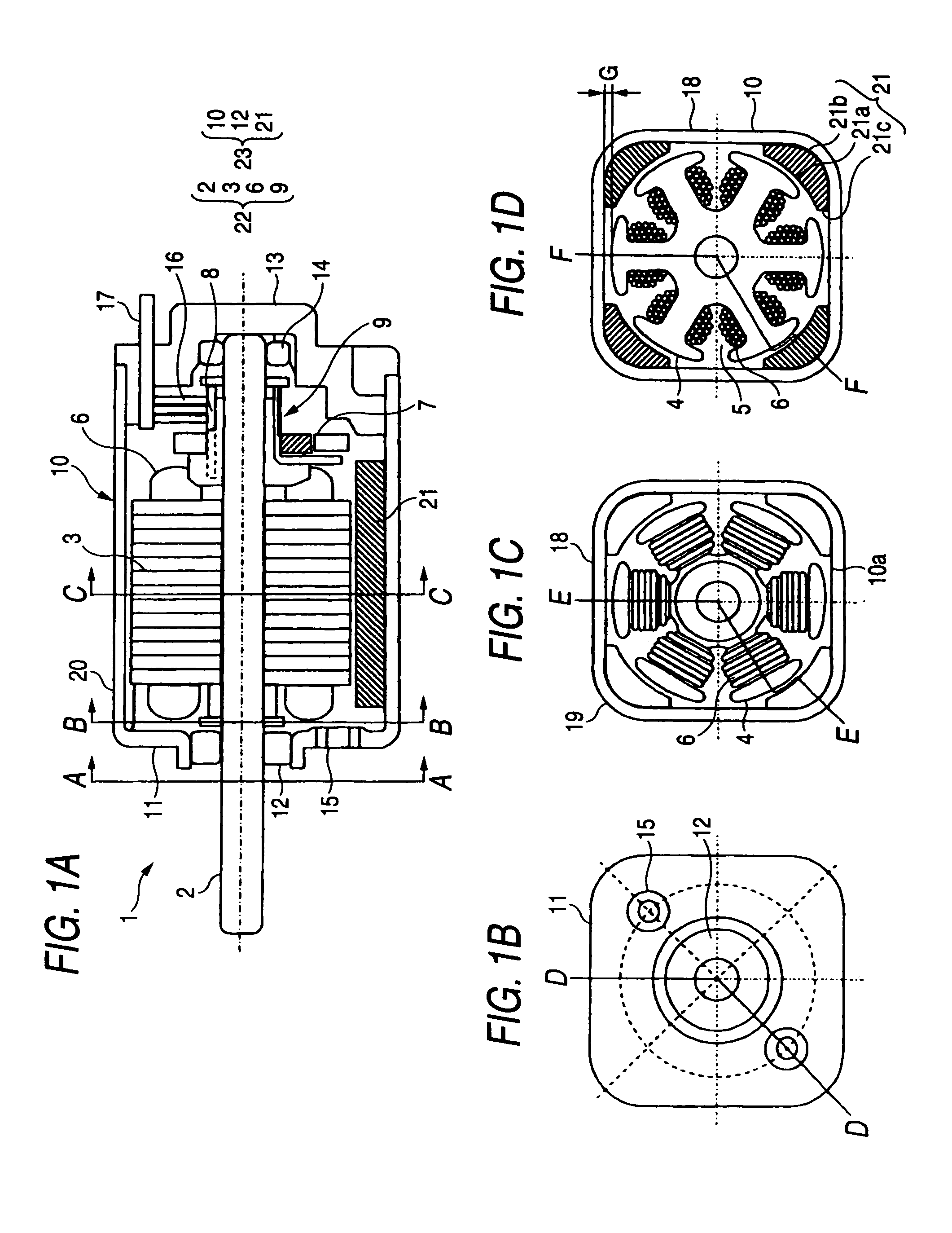
[0050]FIGS. 1A to 1D are drawings which illustrate the configuration of a small DC motor according to Embodiment 1 of the invention. In Embodiment 1, a case will be described in which an armature assembly has an armature core.

[0051]FIG. 1A is a sectional view taken along a longitudinal direction of a shaft, and in FIG. 1A, a segment from line A-A to line B-B is a sectional view taken along line D-D in FIG. 1B, a segment from line B-B to line C-C is a sectional view taken along line E-E in FIG. 1C, and a segment from line C-C to an end block is a sectional view taken along line F-F in FIG. 1D. FIG. 1B is a sectional view taken along line A-A in FIG. 1A, FIG. 1C is a sectional view taken along line B-B in FIG. 1A, and FIG. 1D is a sectional view taken along line C-C in FIG. 1A.

[0052]A small DC motor 1 illustrated in FIG. 1A has an armature assembly 22 and a frame assembly 23.

[0053]The armature assembly 22 has a shaft 2, an armature core 3 provided on the shaft 2, armature windings 6 w...

embodiment 2

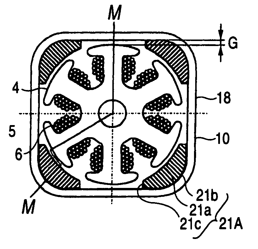
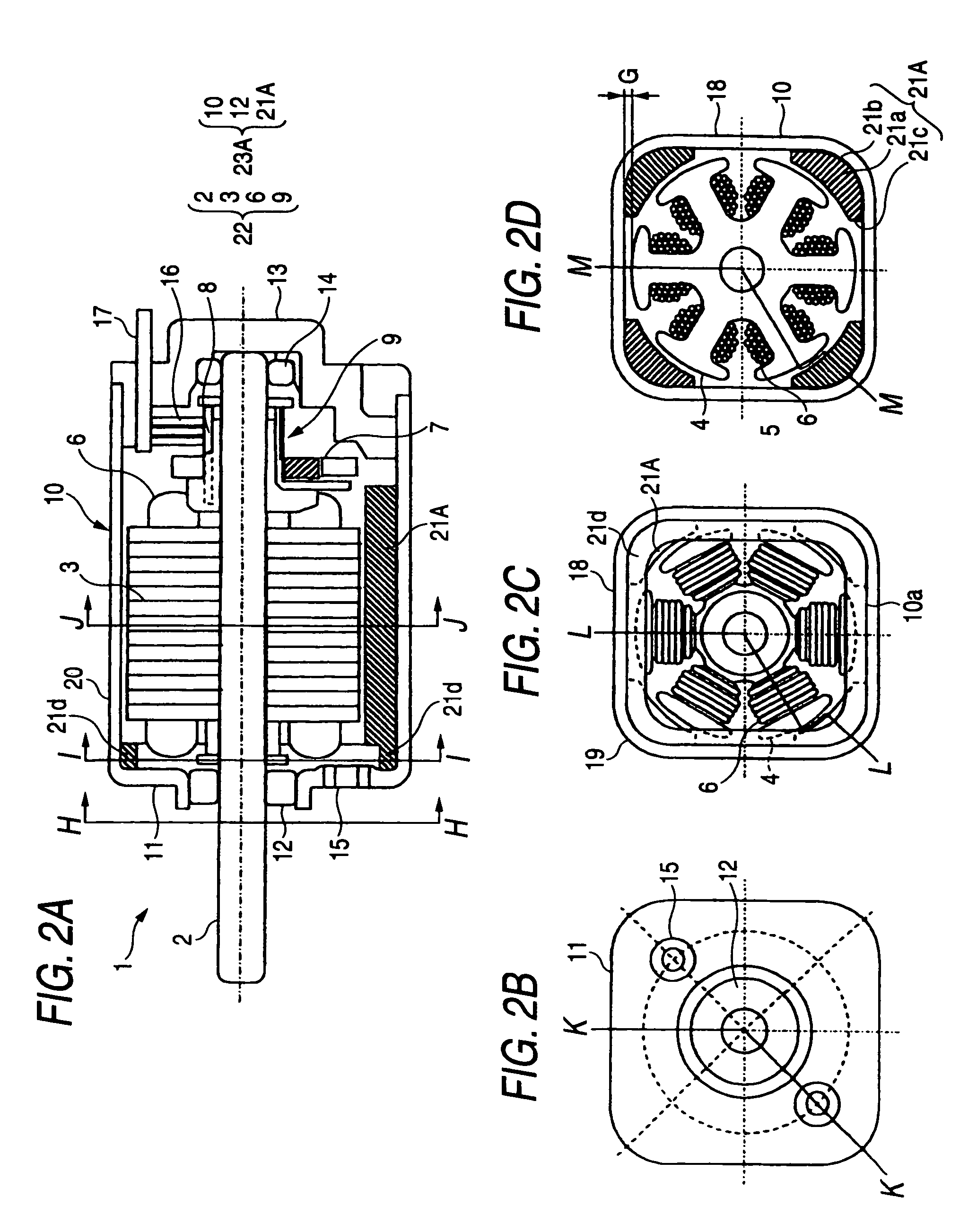
[0072]FIGS. 2A to 2D are drawings which illustrate the configuration of a small DC motor according to another embodiment of the invention.

[0073]FIG. 2A is a sectional view taken along a longitudinal direction of a shaft, and in FIG. 2A, a segment from line H-H to line I-I is a sectional view taken along line K-K in FIG. 2B, a segment from line I-I to line J-J is a sectional view taken along line L-L in FIG. 2C, and a segment from line J-J to an end block is a sectional view taken along line M-M in FIG. 2D.

[0074]FIG. 2B is a sectional view taken along line H-H in FIG. 2A, FIG. 2C is a sectional view taken along line I-I in FIG. 2A, and FIG. 2D is a sectional view taken along line J-J in FIG. 2A.

[0075]FIG. 2 has the same constituent elements except for field magnets as those of FIG. 1. Like reference numerals are given to like constituent elements, and the description thereof will be omitted.

[0076]A small DC motor 1 illustrated in FIG. 2A has an armature assembly 22 and a frame assemb...

embodiment 3

[0081]FIGS. 3A and 3B are drawings which illustrate the configuration of a small DC motor 1 according to a further embodiment of the invention. In addition, armature windings are omitted from the drawing. FIG. 3A is a sectional view which illustrates a cross section of a motor frame having a plurality of curved surfaces for 4 poles and 6 slots, FIG. 3B is a sectional view which illustrates a cross section of an octagonal motor frame for 8 poles and 12 slots, and FIG. 3C is a sectional view which illustrates a cross section of a square motor frame for 4 poles and 6 slots.

(Shapes of Motor Frame)

[0082]The motor frames of the aforesaid embodiments take the quadrangular shape as the basic shape thereof and are formed into the shape in which in the cross section of the motor frame resulting when the corner portions are collapsed inwardly while part of each of the sides of the quadrangular shape is left intact, the adjacent but spaced-apart sides of the motor frame are connected by the arc...


PUM


Abstract

A small DC motor includes: a motor frame including a cylindrical portion, the cylindrical portion having a constant thickness and having a cross section in a shape that includes four sides and connecting portions, each of the connecting portions connecting adjacent two of the four sides and being located inward from a corresponding corner in a quadrangle including the four sides; field magnets; and an armature assembly, wherein the field magnets are provided so as to be spaced apart from each other, and the small DC motor includes an air gap between each of the four sides and a radially outermost surface of the armature assembly, the air gap being a minimum size needed to rotate the armature assembly.

Description

BACKGROUND OF THE INVENTION[0001]1. Field of the Invention[0002]The invention relates to a small DC (direct current) motor, and more particularly to a small DC motor which is small in size but which has a large torque.[0003]2. Background Art[0004]In the field of small DC motors, there is an increasing tendency to demand motors small in size and light in weight. In DC motors which have cylindrical motor frames having circular cross sections, there is caused a limitation on a relationship between the shape of a field magnet and necessary magnetization characteristics, and in addition, a separate mounting configuration becomes necessary.[0005]In contrast, in DC motors which have motor frames having quadrangular cross sections, necessary magnetization characteristics or magnetic properties which appear as if they matched a sinusoidal magnetization curve can be generated by increasing the thickness of a field magnet at a corner portion of the motor frame, so that the motor frame can be f...

Claims


Application Information

Patent Timeline
Patent Type & Authority Patents(United States)
IPC IPC(8): H02K21/26
CPCH02K23/04
Inventor KURODA, MINORU
Owner MINEBEA MOTOR MFG
Why Eureka
Try Eureka