Method for magnetizing ring magnet and magnetic encoder

a technology which is applied in the field of magnetizing ring magnets and magnetic encoders, can solve the problems of degrading the accuracy of detecting the angle of rotation, the effect of noise components

Active Publication Date: 2009-03-03
HARMONIC DRIVE SYST IND CO LTD
View PDF7 Cites 48 Cited by
  • Summary
  • Abstract
  • Description
  • Claims
  • Application Information

AI Technical Summary

Benefits of technology

[0008]It is also an object of the present invention to provide a magnetic encoder in which a ring magnet that is bipolarly magnetized in an appropriate fashion is used to enable the accurate detection of the angle of rotation and the like.
[0012]In the magnetizing method according to the present invention, bipolar magnetization is performed in a state in which the inner circumferential surface of a magnetic ring is covered by an insertion member that has substantially the same magnetic permeability as the magnetic ring. Bending of the direction of magnetic flux in the inner circumferential surface of the magnetic ring can therefore be avoided, unlike the case in which the inner circumferential surface of the magnetic ring forms an interface with air, which has a different magnetic permeability. The extent to which the magnetic flux formed within the magnetic ring is inclined relative to the parallel magnetic field can therefore be minimized.
[0013]The harmonic noise included in the detection output of the rotational magnetic field of a ring magnet that is bipolarly magnetized in this fashion can therefore be minimized in magnetic sensors in which this magnet is used. Therefore, a lowering of the detection accuracy of a magnetic encoder due to the state of magnetization of the ring magnet can be minimized by using a ring magnet bipolarly magnetized according the method of the present invention.
[0016]In the magnetizing method according to the present invention, bipolar magnetization is performed in a state in which the outer circumferential surface of a magnetic ring is covered by an encircling member that has substantially the same magnetic permeability as the magnetic ring. Bending of the direction of magnetic flux in the outer circumferential surface of the magnetic ring can therefore be avoided, unlike the case in which the outer circumferential surface of the magnetic ring forms an interface with air, which has a different magnetic permeability. The extent to which the magnetic flux formed within the magnetic ring is inclined relative to the parallel magnetic field can therefore be minimized.
[0017]The harmonic noise included in the detection output of the rotational magnetic field of a ring magnet that is bipolarly magnetized in this fashion can therefore be minimized in magnetic sensors in which this magnet is used. Therefore, a lowering of the detection accuracy of a magnetic encoder due to the state of magnetization of the ring magnet can be minimized by using a ring magnet bipolarly magnetized according to the method of the present invention.

Problems solved by technology

As a result, an adverse effect occurs in which the noise components have the effect of degrading the accuracy of detecting the angle of rotation when this ring magnet 2 is used in the fabrication of the magnetic encoder shown in FIG. 6(a).

Method used


Image

  • Method for magnetizing ring magnet and magnetic encoder
  • Method for magnetizing ring magnet and magnetic encoder
  • Method for magnetizing ring magnet and magnetic encoder

Examples


embodiment 1

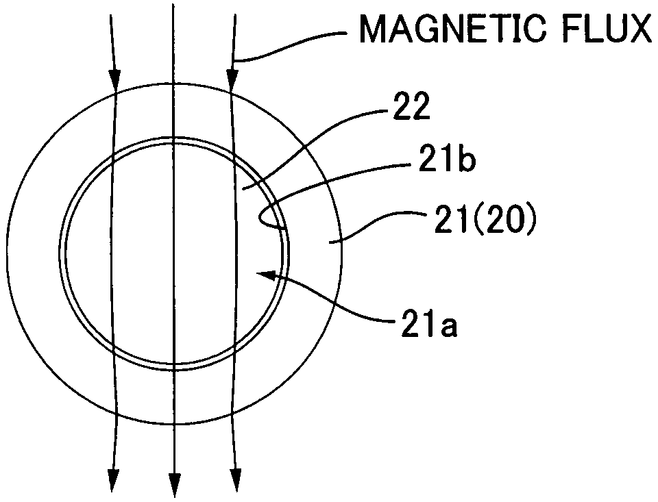
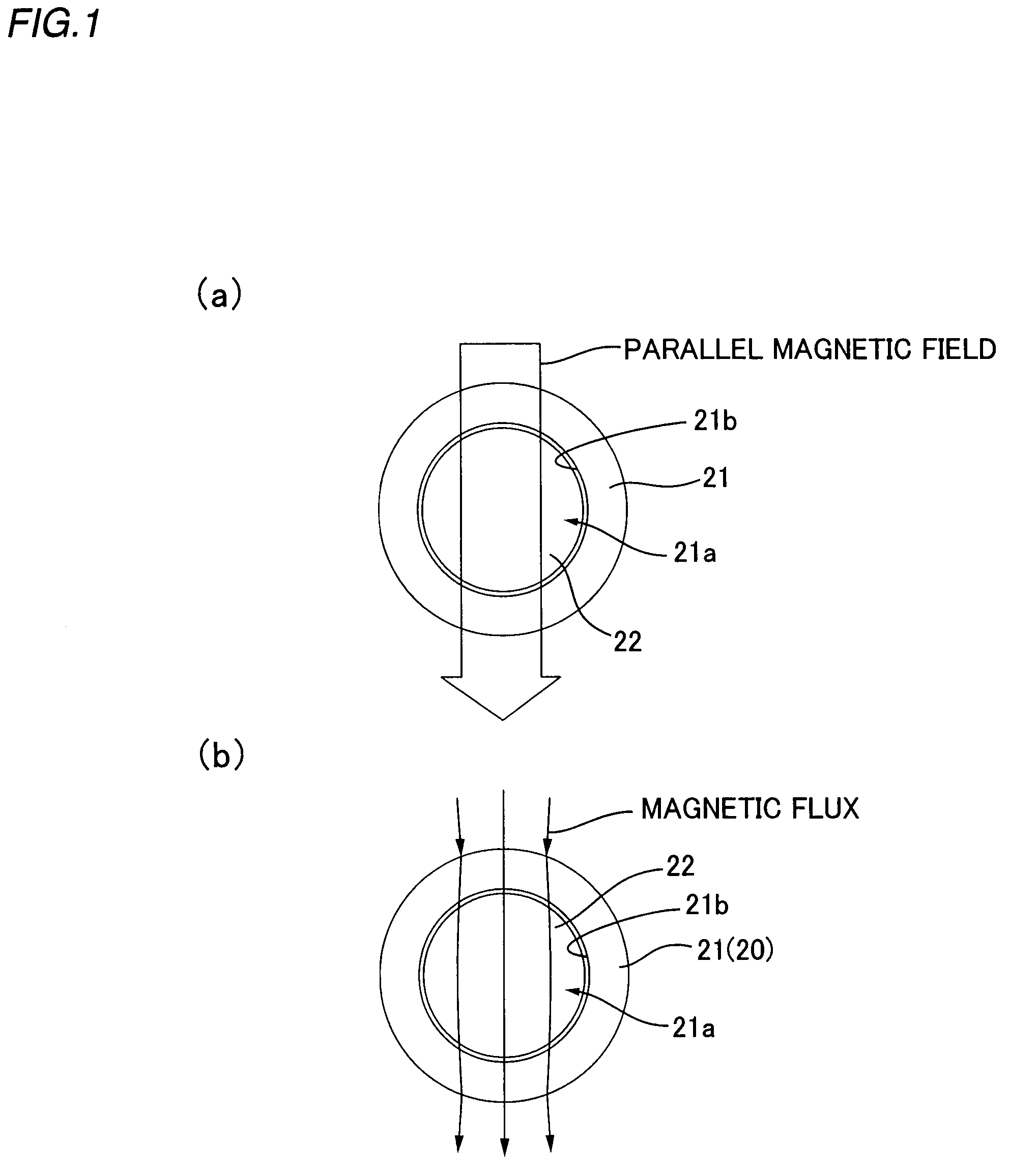
[0031]FIG. 1 is a descriptive diagram that shows an example of the method for magnetizing a ring magnet. A magnetic ring 21 having a central circular hole 21a is produced, as shown in FIG. 1(a). A cylindrical insertion member 22 is constructed from a material having substantially the same magnetic permeability as the magnetic ring 21. The outside diameter of the insertion member 22 allows the insertion member 22 to be removably fit inside the central circular hole 21a. A cylindrical insertion member 22 that has the same magnetic permeability as the magnetic ring 21 may be constructed from, e.g., the same material as the magnetic ring 21. The thickness (the length in the axial direction) of the cylindrical insertion member 22 is preferably equal to or greater than the thickness of the magnetic ring 21.

[0032]The cylindrical insertion member 22 is then fit into the central circular hole 21a of the magnetic ring 21 (insertion member mounting step). As a result, the circular inner circum...

embodiment 2

[0036]FIG. 3 is a descriptive diagram that shows another example of the method for magnetizing a ring magnet according to the present invention. In the method of the present example, a magnetic ring 41 is structured to form a central circular hole 41a, as shown in FIG. 3(a). A cylindrical insertion member 42 is constructed from a material having substantially the same magnetic permeability as the magnetic ring 41. The outside diameter of the insertion member 42 allows the insertion member 42 to be removably fit inside the central circular hole 41a. A cylindrical insertion member 42 that has the same magnetic permeability as the magnetic ring 41 may be constructed from, e.g., the same material as the magnetic ring 41. The thickness (the length in the axial direction) of the cylindrical insertion member 42 is preferably equal to or greater than the thickness of the magnetic ring 41.

[0037]A rectangular encircling member 43 provided with a circular hollow part 43a having an inside diame...


PUM

PropertyMeasurementUnit
magnetic permeabilityaaaaaaaaaa
magnetic fieldaaaaaaaaaa
diameteraaaaaaaaaa

Abstract

An insert member (42) having an identical permeability is fitted in the circular center hole(41a) of a magnetic ring (41) which is then fitted in the circular hollow section (43a) of a fitting-over member (43) having an identical permeability. Under that state, the magnetic ring (41) is placed in a parallel magnetic field. Lines of magnetic flux passing through the magnetic ring (41) held between the insert member (42) and the fitting-over member (43) become linear without substantially inclining against the parallel magnetic field. Under that state, harmonic noise causing a deterioration in detection precision will scarcely appear in the output of a magnetic sensor for detecting the rotating magnetic field of a ring magnet (40) obtained by performing two-pole magnetization on the magnetic ring (41). When the ring magnet (40) is employed, a deterioration in the detection precision of a magnetic encoder (1) due to the magnetization state of the ring magnet (40) can be avoided, and the deterioration in detection precision can be suppressed.

Description

TECHNICAL FIELD[0001]The present invention relates to an improved method for magnetizing a bipolarly magnetized ring magnet for use in a magnetic encoder or the like, and further relates to a magnetic encoder whose detection accuracy is improved by using a ring magnet that has been bipolarly magnetized by the improved method.BACKGROUND ART[0002]Well-known magnetic encoders for detecting the rotation angle and other quantities of a rotating body include devices provided with a bipolarly magnetized ring magnet, as shown in FIG. 6(a). In such a magnetic encoder 1, a bipolarly magnetized ring magnet 2 is attached so as to rotate integrally with the rotating body to be detected (not shown). Two magnetic sensors 3X, 3Y are positioned at a 90-degree angular spacing in the circumferential direction facing the outer circumferential surface 2a of the ring magnet 2 across a set gap.[0003]When the ring magnet 2 rotates together with the rotating body, sinusoid detection signals that are shifted...

Claims


Application Information

Patent Timeline
Patent Type & Authority Patents(United States)
IPC IPC(8): H01F13/00H01F7/20
CPCH01F41/0273H01F13/003
Inventor MIYASHITA, KUNIOKOYAMA, JUNJIMITAMURA, MUNEOSAWAMURA, YASUO
Owner HARMONIC DRIVE SYST IND CO LTD
Why Eureka
Try Eureka