Pressing direction sensor and input device using the same

a technology of pressing direction sensor and input device, which is applied in the direction of static indicating device, instrument, sport apparatus, etc., can solve the problems of structural thickness of mechanism types, limitations of portable devices to which it can be mounted,

Inactive Publication Date: 2009-03-03
FUJITSU COMPONENENT LTD
View PDF20 Cites 14 Cited by
  • Summary
  • Abstract
  • Description
  • Claims
  • Application Information

AI Technical Summary

Benefits of technology

[0009]It is therefore an object of the present invention to provide a small and thin pressing direction sensor that can continually detect pressing directions in the angle range of 360 degrees, having a different structure from the prior arts disclosed in the above described patent publications.

Problems solved by technology

However, any of those types of mechanisms structurally requires a certain thickness, and of course has limitations on portable devices to which it can be mounted.

Method used


Image

  • Pressing direction sensor and input device using the same
  • Pressing direction sensor and input device using the same
  • Pressing direction sensor and input device using the same

Examples


first embodiment

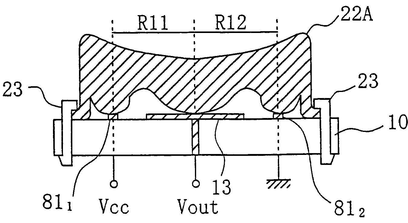
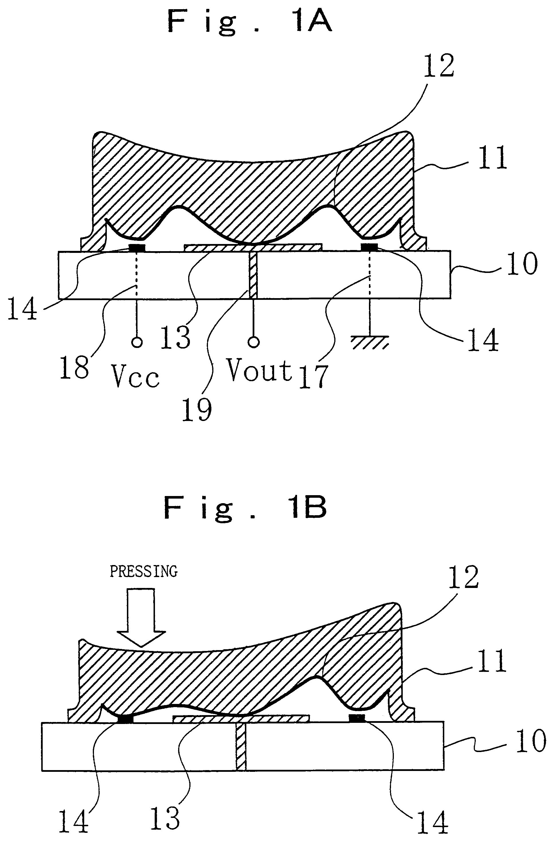
[0050]FIGS. 1A and 1B are sectional views of a pressing direction sensor according to the first embodiment of the present invention. FIG. 1A illustrates the stationary state of the sensor, and FIG. 1B illustrates the operation state of the sensor.

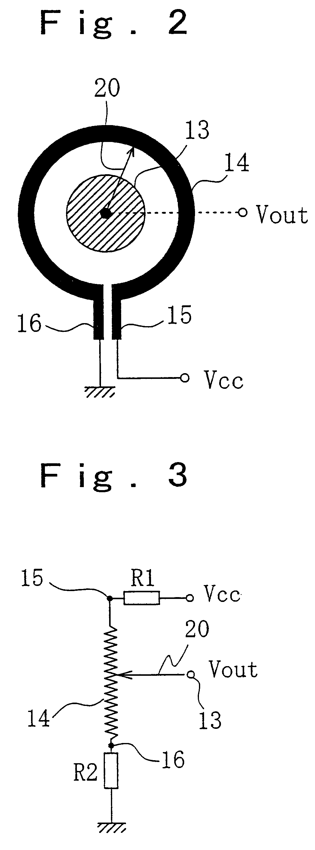
[0051]The pressing direction sensor shown in FIGS. 1A and 1B includes a printed wiring board 10 and a pressing member. Patterns shown in FIG. 2 are formed on the surface of the printed wiring board 10. A pattern 13 is a round electrode pattern, and a pattern 14 is a ring-shaped resistive film pattern surrounding the pattern 13. The printed wiring board is formed of an insulating material, and has the patterns 13 and 14 printed thereon. The resistive film 14 is a resistive carbon film having linear characteristics, for example. The center of the electrode pattern 13 corresponds to the center of the resistive film pattern 14. In other words, the electrode pattern 13 and the resistive film pattern 14 are concentrically arranged. The resistive ...

second embodiment

[0055]FIGS. 4A and 4B are sectional view showing a pressing direction sensor according to a second embodiment of the present invention. FIG. 4A illustrates the stationary state of the pressing direction sensor, and FIG. 4B illustrates a pressed state thereof. In FIGS. 4A and 4B, the same components as descried in the first embodiment are denoted by like reference numerals. Further, FIG. 5 shows a pattern formed on the surface of the printed wiring board 10, and FIGS. 6A and 6B show the detection circuit. The pressing direction sensor according to the second embodiment is characterized by being able to detect pressing force as well as the pressing direction.

[0056]As shown in FIGS. 4A, 4B, and 5, the pressing direction sensor of this embodiment further includes a ring-like electrode pattern 21. Hereinafter, the above described electrode pattern 13 will be referred to as a first electrode pattern, and the electrode pattern 21 a second electrode pattern. The second electrode pattern 21 ...

third embodiment

[0060]FIG. 7 is a sectional view of a pressing direction sensor according to a third embodiment of the present invention. FIG. 8 shows a pattern formed on the surface of the printed wiring board 10 shown in FIG. 7. This pressing direction sensor according to the third embodiment has a switch ON / OFF function, as well as the pressing direction detecting function and the pressing force detecting function.

[0061]As shown in FIG. 8, two ring-like electrode patterns 31 and 33 are formed inside the resistive film pattern 14. The resistive film pattern 14 and the electrode patterns 31 and 33 are concentrically arranged. The electrode pattern 31 is equivalent to the second electrode pattern 21 of the second embodiment, and the electrode pattern 33 is equivalent to the first electrode pattern 13 of the second embodiment. One end of an extended line from the electrode pattern 31 extends to the bottom surface of the printed wiring board 10 via a through hole formed in the printed wiring board 10...


PUM

PropertyMeasurementUnit
angleaaaaaaaaaa
resistanceaaaaaaaaaa
pressuresaaaaaaaaaa

Abstract

A small and thin pressing direction sensor that can continually detect pressing directions in the angle range of 360 degrees is provided. This pressing direction sensor includes a ring-like resistive film pattern, a first electrode pattern, and a conductive member that electrically connects the resistive film pattern and the first electrode pattern when pressed. The voltage of the first electrode pattern represents the pressing direction. This pressing direction sensor may further include a second electrode pattern. A signal representing the pressing force can be obtained from the second electrode pattern when the pressed conductive member is brought into contact with the second electrode pattern.

Description

CROSS-REFERENCE TO RELATED APPLICATIONS[0001]This application is a divisional application of application Ser. No. 10 / 335,860, filed Jan. 3, 2003 now U.S. Pat. No. 6,787,865 which is now allowed.BACKGROUND OF THE INVENTION[0002]1. Field of the Invention[0003]The present invention relates to a device for inputting coordinate information into an electronic apparatus, and more particularly, to a pressing direction sensor that can detect pressing directions and pressing forces of a finger pointing on an operation unit.[0004]2. Description of the Related Art[0005]Devices for inputting coordinate information into electronic devices include pointing devices. Pointing devices have been widely used as coordinate input means in personal computers and game machines. In recent years, these pointing devices are sometimes seen on small-size apparatuses such as portable telephones and PDAs, and are therefore expected to become smaller, thinner, lighter, and less costly.[0006]For portable telephones...

Claims


Application Information

Patent Timeline
Patent Type & Authority Patents(United States)
IPC IPC(8): G09G5/08G06F3/038G01L1/20G06F3/033G06F3/0338H01C10/10H01H1/06H01H25/04H01L27/14H01L29/84H01R11/01
CPCG01L1/20G06F3/0338
Inventor ENDO, MICHIKONISHIYAMA, YURIKOKIKUCHI, RYOJIENDO, NORIO
Owner FUJITSU COMPONENENT LTD
Why Eureka
Try Eureka