Flanging device and flanging method with component protection

a technology of flanging device and flanging method, which is applied in the direction of metal working apparatus, manufacturing tools, transportation and packaging, etc., can solve the problems of difficult use of hem in production facilities where different types of body are built, spoiling the aesthetic effect of vehicle body, etc., and achieves the effect of simple handling

Active Publication Date: 2009-03-10
FFT PRODIONSSYST
View PDF18 Cites 91 Cited by
  • Summary
  • Abstract
  • Description
  • Claims
  • Application Information

AI Technical Summary

Benefits of technology

[0007]It is an object of the invention to turn over the rim of a component, preferably vehicle a body part and in particular an outer metal sheet, using simple means, such that the component is not deformed. The device should also be configured such that it can be quickly adapted to different component shapes.
[0010]If the protective structure forms the rolling surface itself, the counter pressure roller does not roll off directly on the component, but on the protective structure which preferably forms a sort of matrix which is adapted to the inner side of the outer contour of the component, such that even the smallest spatial configurations of the component can be exactly copied and deformations need not be feared. The flanging head itself can be a standard type which can also be used for other flanging processes. Above all, this has the advantage that a number of different bodies can be processed for example on a production line for vehicle bodies, preferably automobile bodies. It is merely necessary to retain respectively adapted protective structures which can be initially placed onto the body or inserted in the inner region of the flanging edge, before the flanging process is started.
[0014]In another development, a sensing element is fastened to or formed on the flanging head, preferably pivoted as a sensing roller, in addition to the at least two flanging rollers, and the protective structure forms a guiding path for the sensing element, preferably another rolling surface, which follows the course of the flanging edge. The sensing element, which is guided on the guiding path along the flanging edge in a flanging process, in turn guides the flanging head, enabling the expenditure which has to be made for controlling the movements of the flanging head, in particular the measuring expenditure, to be reduced. For roll-flanging along the flanging edge, it is in principle even possible to completely omit controlling or regulating on the basis of positional signals obtained by measurement. If the flanging head is guided along the flanging edge by means of a sensing element, by guiding the guiding element on a guiding cam which is preferably formed by the protective strip but could in principle for example also be formed by the flanging edge itself, the flanging head is preferably mounted such that it can move back and forth in a direction pointing at least substantially normally with respect to the guiding path, preferably against an elastic restoring force. The elastic restoring force can expediently be a pneumatic force.
[0020]The bearer and the carriage guided on it are in turn mounted on a holder such that they can shift, the holder generally being connected to a robot arm which moves the holder in pre-calculated trajectories. In order to hem over a rim, the robot guides the flanging head along the rim, wherein the shifting bracket of the bearer on the holder enables an automatic equalisation perpendicular to the component. This also equalises tolerances with regard to the orientation of the component relative to a target pre-set which is known to the robot. It is therefore not necessary to separately and exactly detect the actual position of the component, preferably a metal body sheet.
[0023]As mentioned above, it is possible for the bearer to be able to be freely shifted on the holder, within limits. However, in order that movements of the robot arm do not lead to jolting oscillations between the limits, a damper can be arranged between the bearer and the holder.

Problems solved by technology

The problem here is that the outer side of the outer shell should not be deformed or at least deformed as little as possible, i.e. must not for example receive any dents or scratches, since these would be immediately visible when the outer shell is subsequently painted, and would spoil the aesthetic effect which the vehicle body is intended to impart.
Since a counter pressure is omitted here, the quality of the hem is not always satisfactory.
Moreover, this is relatively involved equipment which only caters specifically for the body of one type of vehicle in each case, which makes using it in production facilities in which different types of body are built problematic.

Method used


Image

  • Flanging device and flanging method with component protection
  • Flanging device and flanging method with component protection
  • Flanging device and flanging method with component protection

Examples


Embodiment Construction

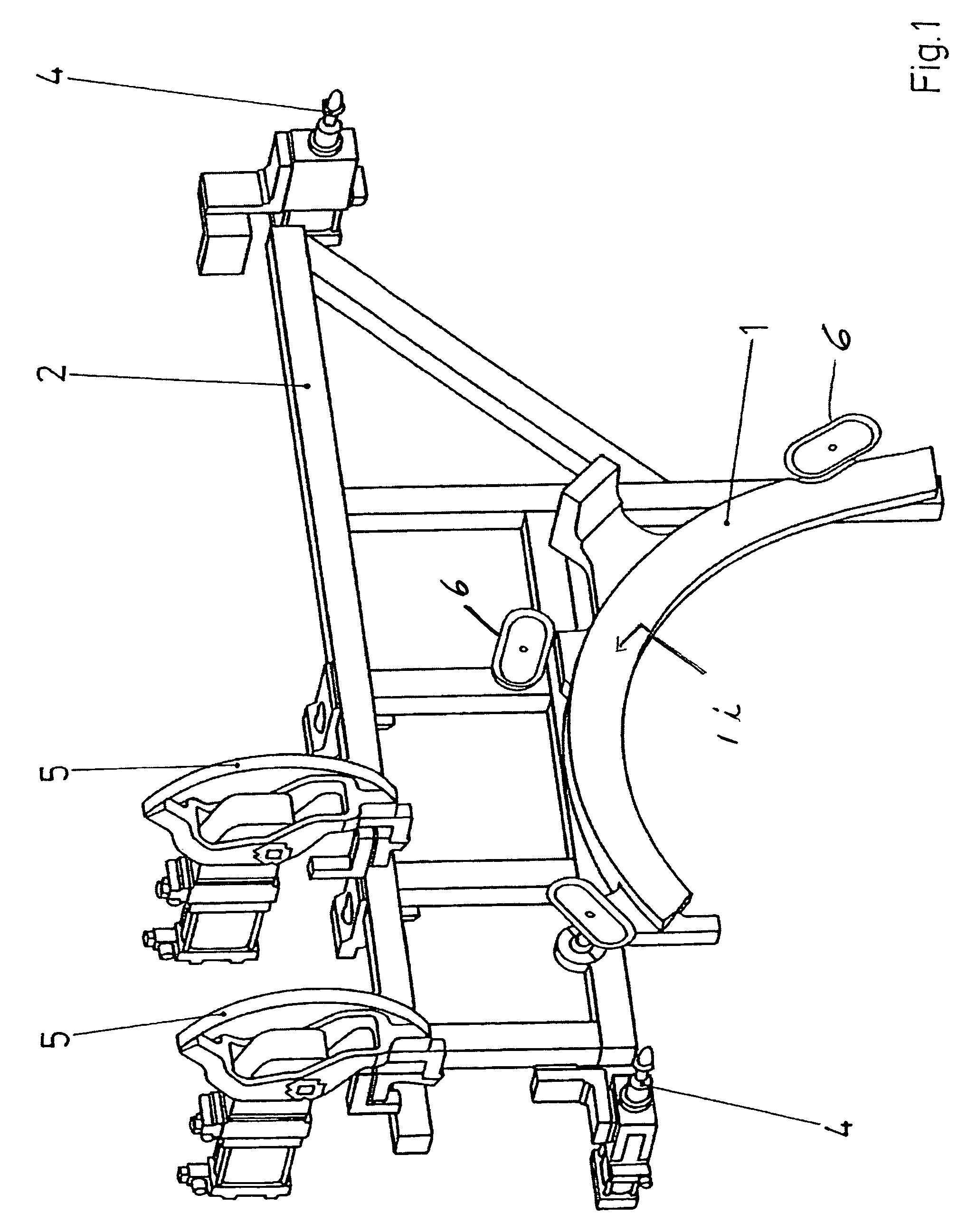
[0038]FIG. 1 shows a protective strip 1 in a framework 2 in accordance with the present invention. As will be recognised, the protective strip 1 follows the course of a wheel section. Its inner side 1i, visible in the figure, exhibits a contour which copies the desired outer contour of the body on the wheel arch, as a negative. The outer contour is generally in no way smooth, but is often provided with different facets and vertical structures, in order to obtain a particular aesthetic effect and / or a smooth transition to the adjacent body portions. On no account should this contouring be breached.

[0039]The framework 2 comprises a number of markers in the form of positioning pins 4 which engage with corresponding holes in the body, whereby the protective strip 1 is definitively fixed with respect to the body. Mechanical clamps 5 hold the framework 2 and therefore the protective strip 1 clamped on the body.

[0040]The outer side of the protective strip 1 is smooth and forms a rolling su...


PUM

PropertyMeasurementUnit
hemming angleaaaaaaaaaa
angleaaaaaaaaaa

Abstract

A flanging device for roll-flanging a rim of a component includes a flanging head, a first flanging roller which is mounted by the flanging head and can be rolled off on the rim during roll-flanging, and a second flanging roller which is mounted by the flanging head and forms a counter pressure roller for the first flanging roller, the flanging device including a stable protective structure which is or can be fastened to the component and forms a rolling surface for one of the flanging rollers or supports a rolling surface.

Description

RELATED APPLICATIONS[0001]Pursuant to 35 U.S.C. § 119, this application claims priority to German Patent Application No. 10 2004 046 432.4, filed Sep. 24, 2004, and to German Utility Application No. 20 2005 005 880.7, filed Apr. 13, 2005, the contents of both applications being incorporated by reference herein.FIELD OF THE INVENTION[0002]The invention relates to a flanging device for roll-flanging a rim of a component or other work piece along a flanging edge, and to a flanging method.BACKGROUND OF THE INVENTION[0003]The situation presented, in which an outer part of the body has to be connected to an inner part by hemming, arises for example in the case of wheel arches of vehicle bodies. The outer shell of the body has a circular arced, preferably semi-circular section, on the rim of which the so-called wheel arch is fastened on the inner side of the body. The problem here is that the outer side of the outer shell should not be deformed or at least deformed as little as possible, i...

Claims


Application Information

Patent Timeline
Patent Type & Authority Patents(United States)
IPC IPC(8): B21D7/02B21D9/08B23P11/00
CPCB21D39/021B21D39/023Y10T29/53791B62D65/16B60Y2304/072
Inventor QUELL, EWALD
Owner FFT PRODIONSSYST
Why Eureka
Try Eureka