
Sealing ring with improved fastener

a technology of sealing rings and fasteners, applied in the direction of clamping mechanisms, fastening means, packaging, etc., can solve the problems of difficult access, difficulty in and difficulty in completing otherwise relatively simple yet precise tasks. , to achieve the effect of preventing or detecting unauthorized tampering or removal of meters

Active Publication Date: 2009-03-10
THOMAS & BETTS INT INC
View PDF31 Cites 20 Cited by
  • Summary
  • Abstract
  • Description
  • Claims
  • Application Information

AI Technical Summary

Benefits of technology

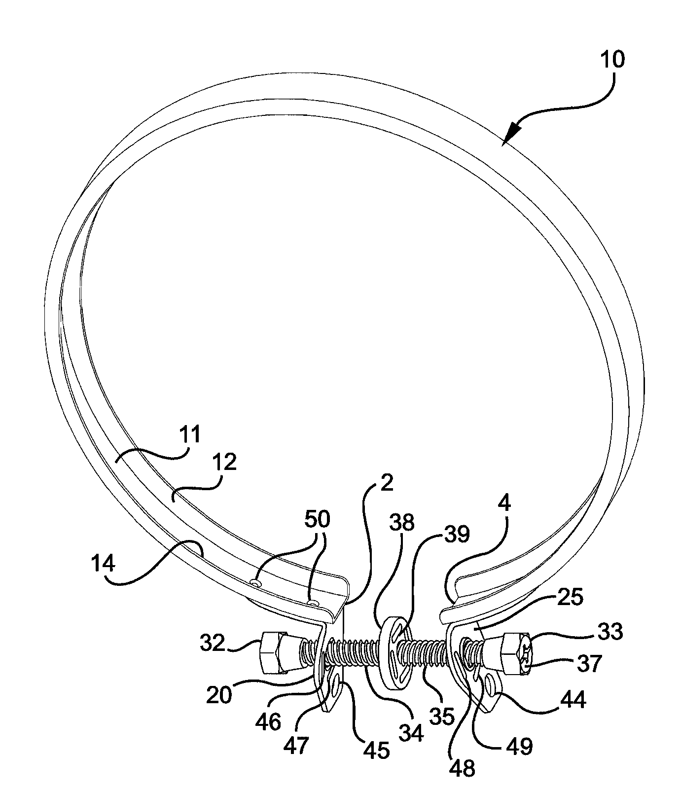
"The present invention provides a sealing ring for watt-hour meters that prevents unauthorized tampering or removal of the meter. The sealing ring has a split-ring annular band with tabs on each end that secure the meter and its cover to the meter box. The tabs have threaded apertures that are different from each other, and a fastener is engaged with the apertures to adjust the radial dimension of the annular band. The fastener can include ergonomic features for easy adjustment and can align with tab slots or have slots that align with tab slots. The sealing ring can also include a wheel or slots for a security device. The method of securing the sealing ring on the meter involves positioning the sealing ring and rotating the fastener. The technical effects of this invention are improved security and prevention of unauthorized tampering or removal of the meter."

Problems solved by technology

Installation of sealing rings can be cumbersome and time consuming.
However, many watt-hour meters are located outdoors, often covered or encroached upon by structures, conduits, cables and surrounding flora, and are difficult to access.
Add to this, poor weather conditions, low lighting or uneven terrain and an otherwise relatively simple yet precise task is made difficult.
Another recognized problem is that most watt-hour meter sealing rings come preassembled and require some disassembly before they are installed.
However, the design of contemporary sealing rings and their fastener screws limit the split-ring aperture, without unthreading the screw from at least one mating tab.
Thus, it is virtually impossible to install a contemporary sealing ring on most meters without unscrewing the screw from at least one tab before completing the installation.
Thus, the installer is now made to spend additional time and effort, first to disassemble the device, before having to reassemble it for the final installation.
Furthermore, upon disassembly, the screw may be dropped and / or lost rendering the device useless.
As discussed above, this can cause difficulties and delays in the final installation.
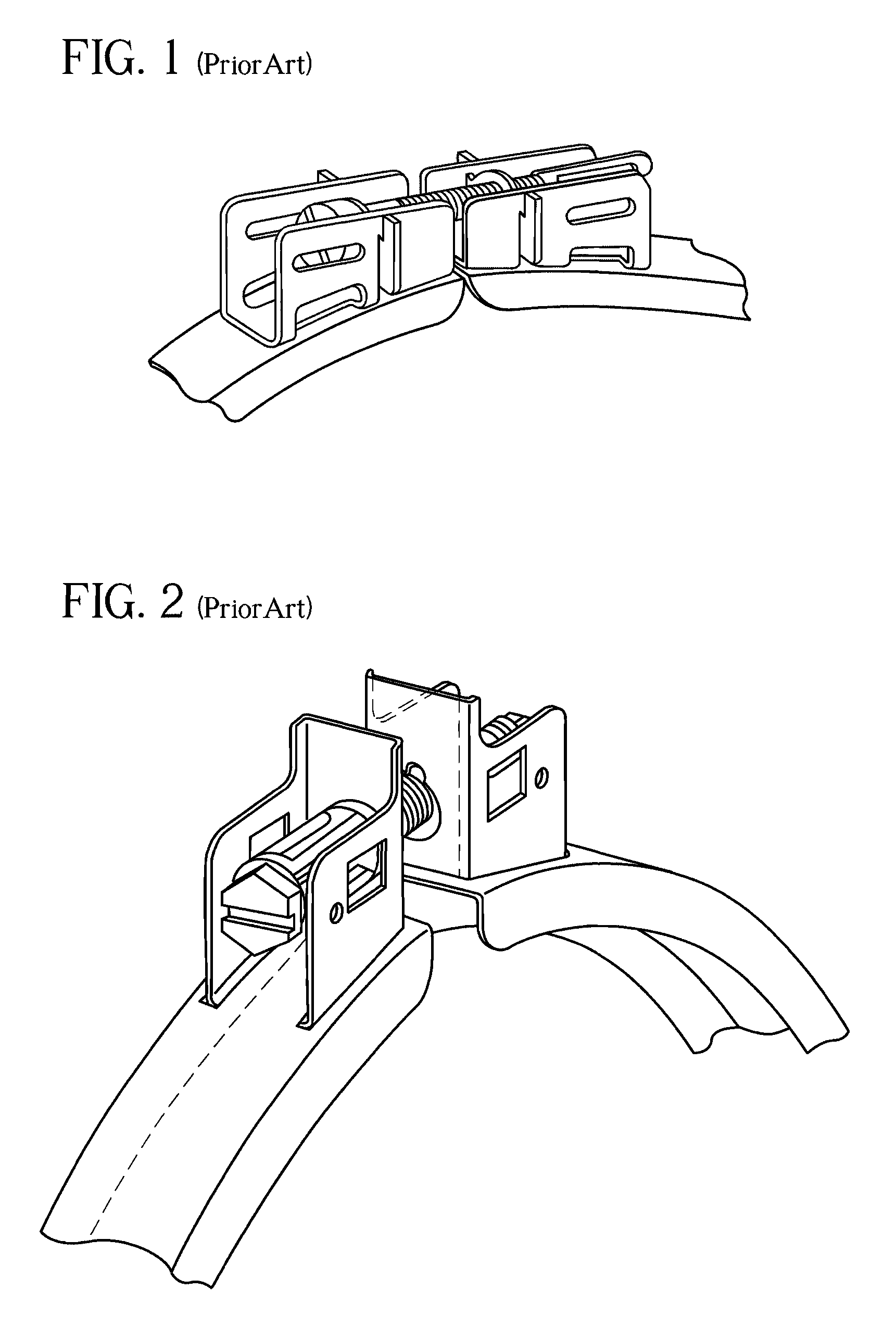
Yet another recognized problem is that the screw that fastens the split ring tabs is difficult to screw-in because it is positioned in the same central plane as the sealing ring itself, which abuts or is in close proximity to the meter base (See FIGS. 1 and 2).
This position makes it very difficult to engage fingers or tools on the screw in order to tighten it for installation, because the longitudinal axis of the screw, and thus the screw heads, is too close to the meter base.
Similar to the screw position problem discussed above, the wire security seal is also difficult to install in prior art sealing rings.
However, once again the close proximity of the sealing ring with the meter base makes it difficult for the installer to weave the small security seal wire through these slots from the front toward the back of the meter and then lock into the security seal slug.
In this way an unauthorized individual can remove the sealing ring assembly without breaking the wire security seal or adjusting the fastener screw.
Additionally, the commonly used screws are difficult to or can not be hand-tightened and often require a specific tool for tightening (as shown by FIG. 1).
This causes even more difficulty during installation, as the installer must be equipped and prepared with the correct tool.
Further still, the overall prior art sealing ring designs are difficult to manufacture.
These designs are also difficult for an installer to manipulate or handle in the field.
The lack of ergonomic holding positions combined with some sharp edges on the piece can even harm the installer.

Method used


Image

  • Sealing ring with improved fastener
  • Sealing ring with improved fastener
  • Sealing ring with improved fastener

Examples


Embodiment Construction

[0031]The present invention, as shown in FIGS. 3 through 8, demonstrates a clamping device in the form of a sealing ring assembly embodying the basic principles and concepts of the present invention. It should be noted that although these figures are directed to the preferred embodiment, other applications of the instant invention are anticipated, as discussed more fully below.

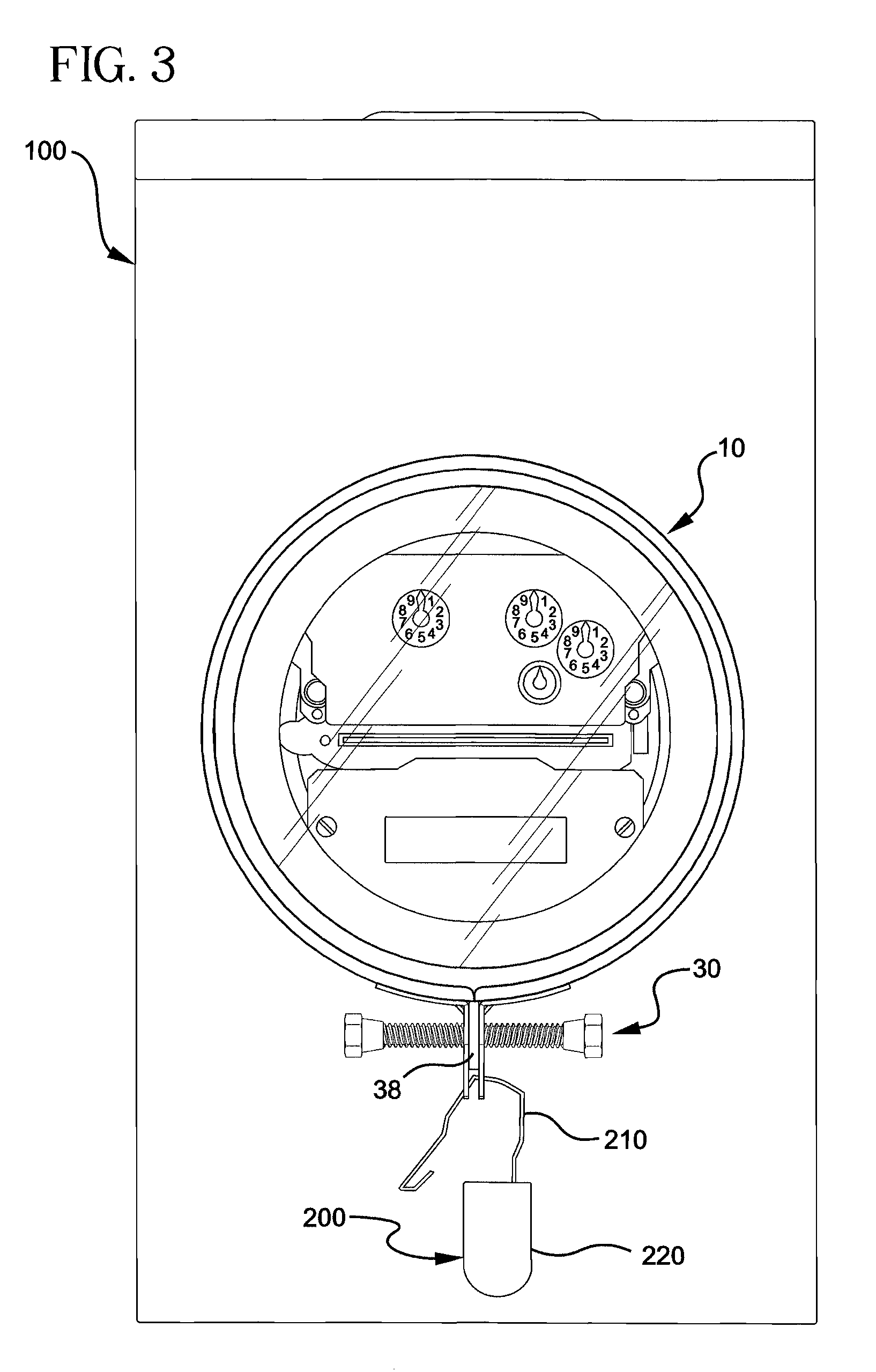
[0032]FIGS. 3 and 4 show a front view and a side view, respectively, of the instant sealing ring assembly 10 installed on a watt-hour meter assembly 100. The actual meter 150 is shown inside the meter cover 160 that is mated to the meter base 110 of the meter box. The sealing ring assembly 10 of the instant invention is shown joining and securing the meter cover 160 to the meter base 110.

[0033]FIGS. 3 and 4 also show that the wire security seal 200 has its wire 210 fed through one of the slots 46, 47, 48, 49 in each support tab 20, 25 as well as through one of the slots 39 in the center fastener wheel 38, alth...


PUM


Abstract

One aspect of the present invention includes a sealing ring having a split-ring annular band which includes a first and second end. A first tab is disposed at the first end, with the first tab extending away from the annular band. The first tab also includes a first threaded aperture. A second tab is disposed at the second end, with the second tab also extending away from the annular band The second tab also includes a second threaded aperture. Additionally, a thread of the first aperture is different from a thread of the second aperture. Further, the sealing ring includes a fastener threadedly engaged with the first and second apertures. Rotation of the fastener adjusts a radial dimension of the annular band.

Description

CROSS-REFERENCE TO RELATED APPLICATIONS[0001]This application claims the benefit of U.S. Provisional Patent Application Ser. No. 60 / 722,666 filed on Sep. 30, 2005.BACKGROUND OF THE INVENTION[0002]The present invention relates generally to a clamping device and more particularly, to sealing rings for electric watt-hour meters.[0003]It is well understood that sealing rings have many applications. They are generally used as clamps for joining or securing cylindrical or annular surfaces. Also, they are particularly used on watt-hour meters that measure the amount of electrical consumption at a particular location, such as a residence or commercial building.[0004]On watt-hour meters, a sealing ring is commonly used to secure the outwardly projecting electrical meter to its meter base. Although each watt-hour meter is secured in a socket in the meter base through frictional and sometimes other means of engagement, sealing rings further prevent the meter from disengaging from its base. Add...

Claims


Application Information

Patent Timeline
Patent Type & Authority Patents(United States)
IPC IPC(8): B65D45/30
CPCF16B5/0275Y10T292/20Y10T292/214
Inventor LALANCETTE, DANIELBOUCHER, YVES
Owner THOMAS & BETTS INT INC
Learn More