Flight control method and apparatus to produce induced yaw

a flight control and yaw technology, applied in the direction of airflow influencers, transportation and packaging, sustainable transportation, etc., can solve the problems of reducing the yaw generation effect, creating additional drag, and changing the drag on the wing section

Active Publication Date: 2009-03-17
FAIRCHILD MARK D
View PDF17 Cites 31 Cited by
  • Summary
  • Abstract
  • Description
  • Claims
  • Application Information

AI Technical Summary

Benefits of technology

[0005]A method of controlling an aircraft in a turn without the use of a rudder by producing Induced Yaw. Induced Yaw being produced by creating a net induced drag dif...

Problems solved by technology

The rudder counterbalances adverse yaw generated by positioning of the ailerons.
The downwash has the effect of increasing the local angle of attack about the wing, which creates additional drag.
With the decrease in lift produ...

Method used


Image

  • Flight control method and apparatus to produce induced yaw
  • Flight control method and apparatus to produce induced yaw
  • Flight control method and apparatus to produce induced yaw

Examples


Embodiment Construction

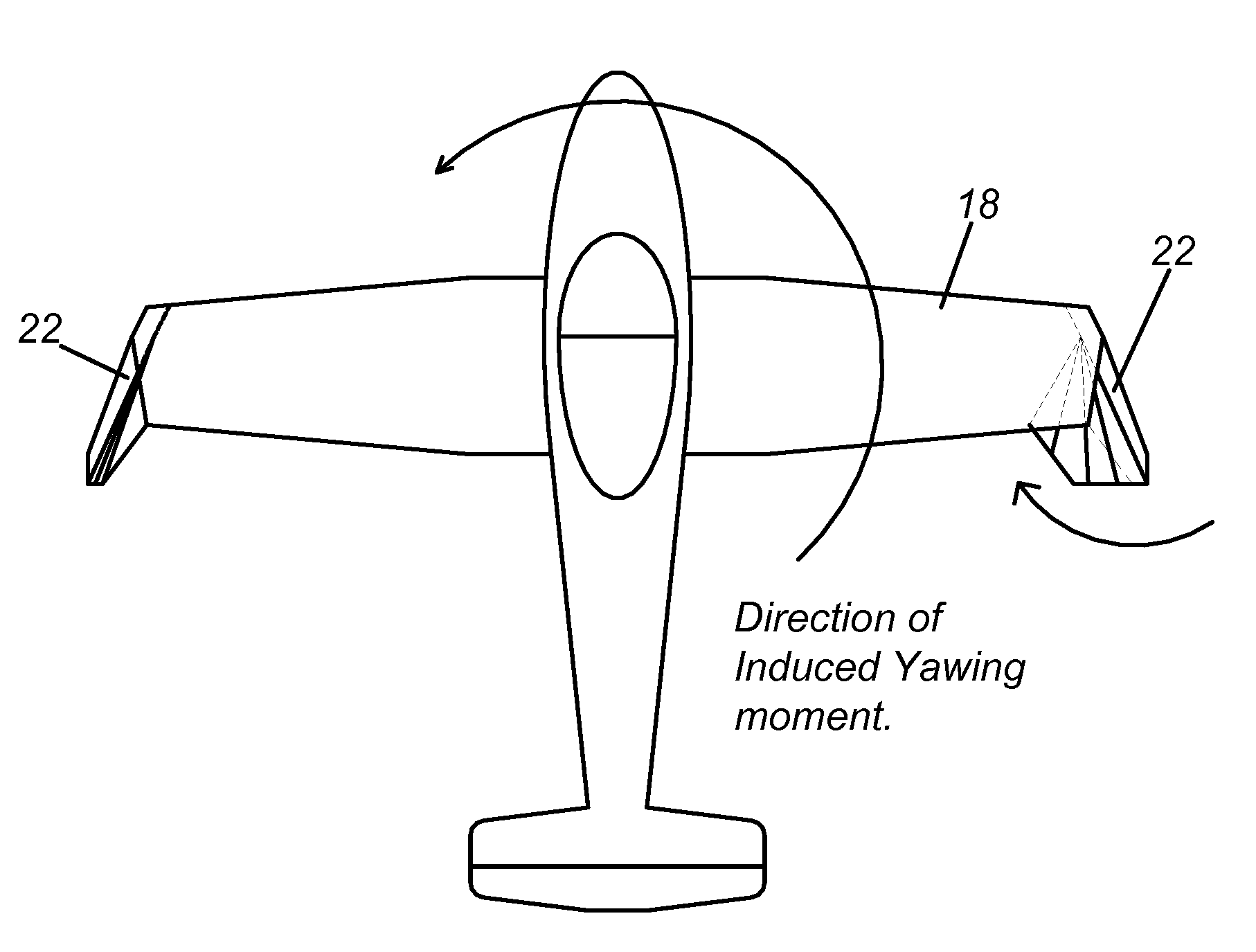
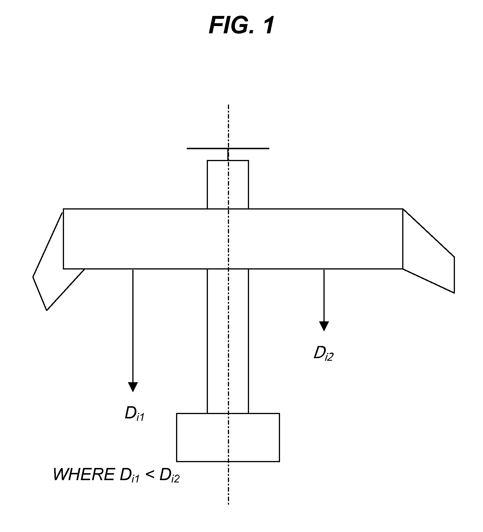
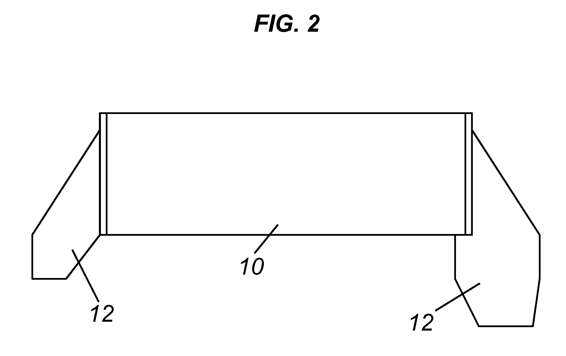
[0014]The present invention is a flight control method and apparatus to provide aircraft flight control for a stable coordinated turn without the use of a rudder. Using aerodynamic theory, it is known to produce a banked turn by adjusting lift produced on the outboard wing and inboard wing of an aircraft. Typically, some form of aileron on each wing is used to adjust the lift of the outboard and inboard wings during a turn. The aileron is usually a hinged surface in the same coordinate plane as the wing near outside ends of the outboard and inboard wings and along the trailing edge of the outboard and inboard wings. A element which is in the same coordinate plane as the wing is referred to as being coplanar. The hinged aileron surface moves up and down within the air flow over the inboard and outboard wings and such movement changes the lift coefficient of each the inboard and outboard wings. The problem is that by increasing the lift of the outboard wing, the amount drag is increas...


PUM


Abstract

A method of controlling an aircraft in a turn without the use of a rudder by producing induced yaw. Induced yaw being produced by creating a net induced drag differential between an inboard wing to the turn and an outboard wing to the turn, whereby the net induced drag differential overcomes adverse yaw produced by the outboard wing.

Description

[0001]This application claims the benefit of and incorporates by reference U.S. Provisional Application No. 60 / 481,941 filed Jan. 22, 2004.BACKGROUND[0002]The present invention generally relates to flight control dynamics of aircraft. More specifically, the present invention relates to flight control dynamics of aircraft which allows a stable coordinated turn without the use of a rudder.[0003]To perform a stable coordinated turn with a fixed wing aircraft, requires the simultaneous use of a horizontal tail, ailerons, and a rudder. The horizontal tail is used for pitch of the aircraft. The ailerons generates increased lift on the outboard wing of the turn and decreased lift on the inboard wing of the turn. The rudder counterbalances adverse yaw generated by positioning of the ailerons. From aerodynamic theory, it is know that having a finite 3-dimensional airfoil such as a wing in a flow will produce 3-dimensional flow about the airfoil. When freestream air flow encounters a wing, a ...

Claims


Application Information

Patent Timeline
IPC IPC(8): B64C3/54
CPCB64C3/54B64C9/34Y02T50/145Y02T50/32Y02T50/10Y02T50/30
Inventor FAIRCHILD, MARK D.
Owner FAIRCHILD MARK D
Why Eureka
Try Eureka