Flight control system for unmanned aerial vehicle

a flight control and unmanned aerial technology, applied in vehicle position/course/altitude control, process and machine control, instruments, etc., can solve the problems of limited data amount and/or data delay, control accuracy may be reduced, and the plurality of flight control units cannot be mounted. achieve favorable redundancy in flight control function, and achieve high-quality flight control

Active Publication Date: 2015-03-12
SUBARU CORP
View PDF1 Cites 32 Cited by
  • Summary
  • Abstract
  • Description
  • Claims
  • Application Information

AI Technical Summary

Benefits of technology

[0008]The present disclosure has been made in consideration of the above-mentioned problem, and provides a flight control system for an unmanned aerial vehicle, the flight control system being capable of achieving redundancy in flight control function favorably while implementing highly accurate flight control even when a certain number of flight control units for ensuring sufficient redundancy may not be mounted in the unmanned aerial vehicle.
[0009]A first aspect of the present disclosure provides a flight control system for an unmanned aerial vehicle including a ground facility. The flight control system controls flight of the unmanned aerial vehicle by a control signal of the unmanned aerial vehicle itself and a control signal from the ground facility. The unmanned aerial vehicle and the ground facility are each provided with at least one flight control unit capable of controlling driving of an airframe actuator that operates parts of the unmanned aerial vehicle based on a sensor output signal from an airframe sensor that detects a flight state of the unmanned aerial vehicle. The at least one flight control unit on the unmanned aerial vehicle and the at least one flight control unit of the ground facility constitute a redundant system for flight control function. In the redundant system for flight control function, one of the at least one flight control unit on the unmanned aerial vehicle serves as a main unit. In the case where a malfunction has occurred in a flight control unit that

Problems solved by technology

However, mounting a plurality of flight control units is definitely not preferable in consideration of weight and mounting space, and may be difficult in the first place due to various restrictions.
However, the technology described in JP-A No. 8-80898 mentioned above adopts a control configuration in which sensor output signals and airframe control signals are constantly transmitted and received via a data link between the airframe and the ground facility, and thus

Method used


Image

  • Flight control system for unmanned aerial vehicle
  • Flight control system for unmanned aerial vehicle

Examples


Embodiment Construction

[0013]Hereinafter, an implementation of the present disclosure will be described with reference to the accompanying drawings.

[Configuration]

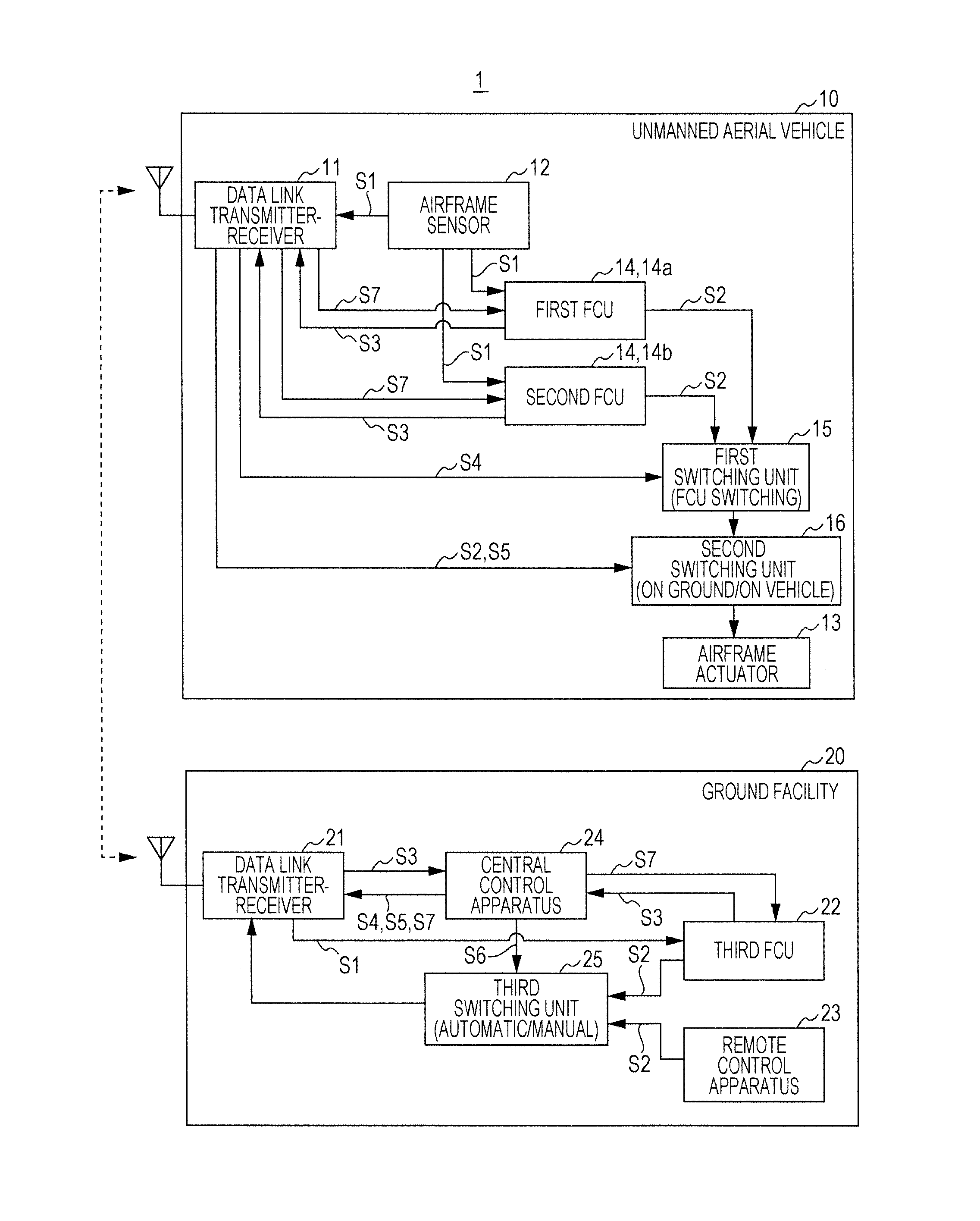
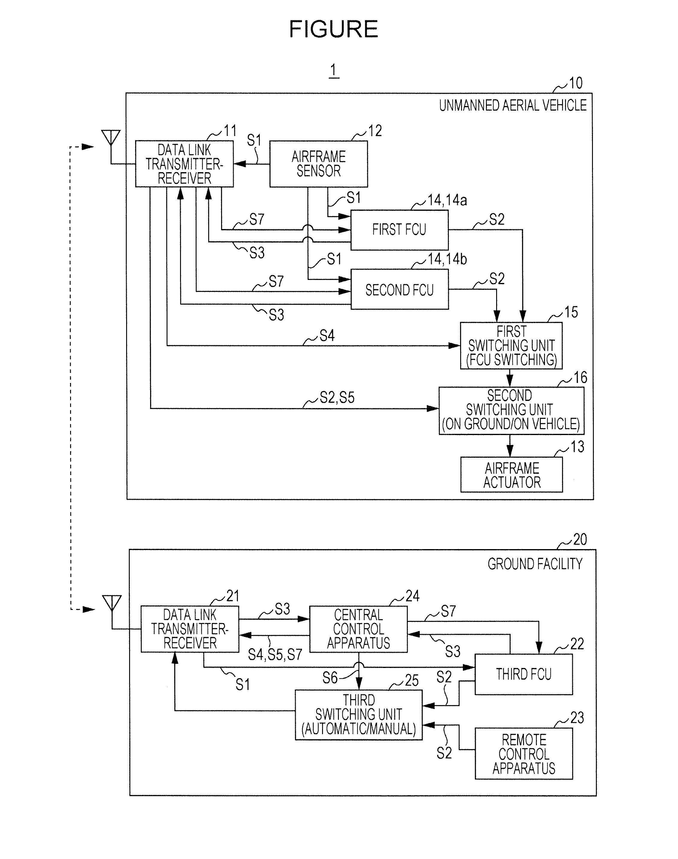
[0014]FIG. 1 is a block diagram illustrating the configuration of a flight control system (hereinafter simply referred to as a “flight control system”) 1 for an unmanned aerial vehicle in the present implementation. As illustrated in FIG. 1, the flight control system 1 controls the flight of an unmanned aerial vehicle 10 by control signals from a ground facility 20.

[0015]The unmanned aerial vehicle 10 includes an airframe sensor 12, an airframe actuator 13, and two flight control units (FCU) 14, in addition to a data link transmitter-receiver 11 which together with the below-described data link transmitter-receiver 21 on the ground facility 20 forms data link and is capable of transmitting and receiving various signals to and from the data link transmitter-receiver 21.

[0016]The airframe sensors 12 are various types of sensors for detecting the f...


PUM


Abstract

A flight control system controls flight of an unmanned aerial vehicle by control signals of the unmanned aerial vehicle itself and from a ground facility. The unmanned aerial vehicle and the ground facility are each provided with at least one flight control unit (FCU) capable of controlling driving of an airframe actuator based on a sensor output signal from an airframe sensor. The at least one FCU on the unmanned aerial vehicle and the at least one FCU of the ground facility constitute a redundant system for flight control function. In the redundant system one of the at least one FCU on the unmanned aerial vehicle serves as a main unit. In the case where a malfunction has occurred in an FCU that performs flight control on the unmanned aerial vehicle, the ground facility is capable of causing another FCU to take over flight control function from the FCU.

Description

CROSS-REFERENCE TO RELATED APPLICATIONS[0001]The present application claims priority from Japanese Patent Application No. 2013-188927 filed on Sep. 12, 2013, the entire contents of which are hereby incorporated by reference.BACKGROUND[0002]1. Technical Field[0003]The present disclosure relates to a flight control system for an unmanned aerial vehicle, and particularly to a useful technology for achieving redundancy in the flight control function of the flight control system.[0004]2. Related Art[0005]In an unmanned aerial vehicle which flies without a pilot, a flight control unit mounted in an airframe typically performs flight control based on a sensor output signal from an airframe sensor and / or a control signal from a ground facility. In order to improve the reliability of flight control in this kind of unmanned aerial vehicle, a plurality of flight control units may be mounted in the airframe so as to achieve redundancy in flight control function. However, mounting a plurality of...

Claims


Application Information

Patent Timeline
IPC IPC(8): B64C39/02B64D43/00
CPCB64D43/00B64C39/024B64U2201/20
Inventor TAKAHASHI, SHINEIMIYATA, KENSHISAKAGUCHI, AKITOSHI
Owner SUBARU CORP
Why Eureka
Try Eureka