Separable electrical connector component having a voltage output branch and a direct access point

a technology of electrical connectors and components, applied in the direction of overvoltage protection resistors, fixed capacitor details, coupling device connections, etc., can solve problems such as “dead-end” or termination

Inactive Publication Date: 2009-03-17
THOMAS & BETTS INT INC
View PDF13 Cites 40 Cited by
  • Summary
  • Abstract
  • Description
  • Claims
  • Application Information

AI Technical Summary

Problems solved by technology

As such, these conventional devices “dead-end” or terminate the access point preventing direct access to the conductor without separation of the connector.

Method used


Image

  • Separable electrical connector component having a voltage output branch and a direct access point
  • Separable electrical connector component having a voltage output branch and a direct access point
  • Separable electrical connector component having a voltage output branch and a direct access point

Examples


Embodiment Construction

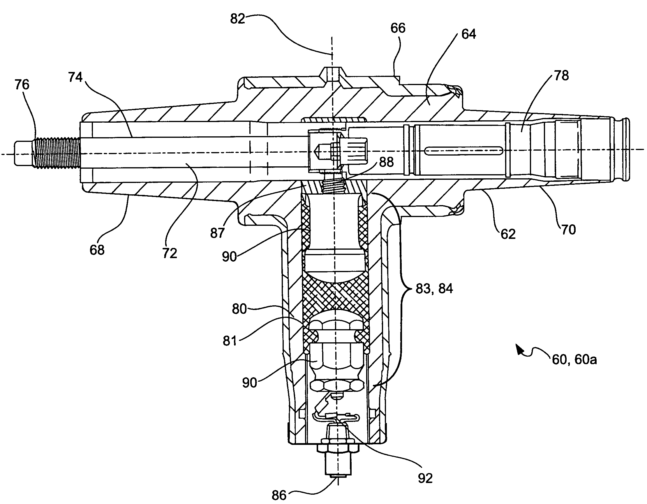
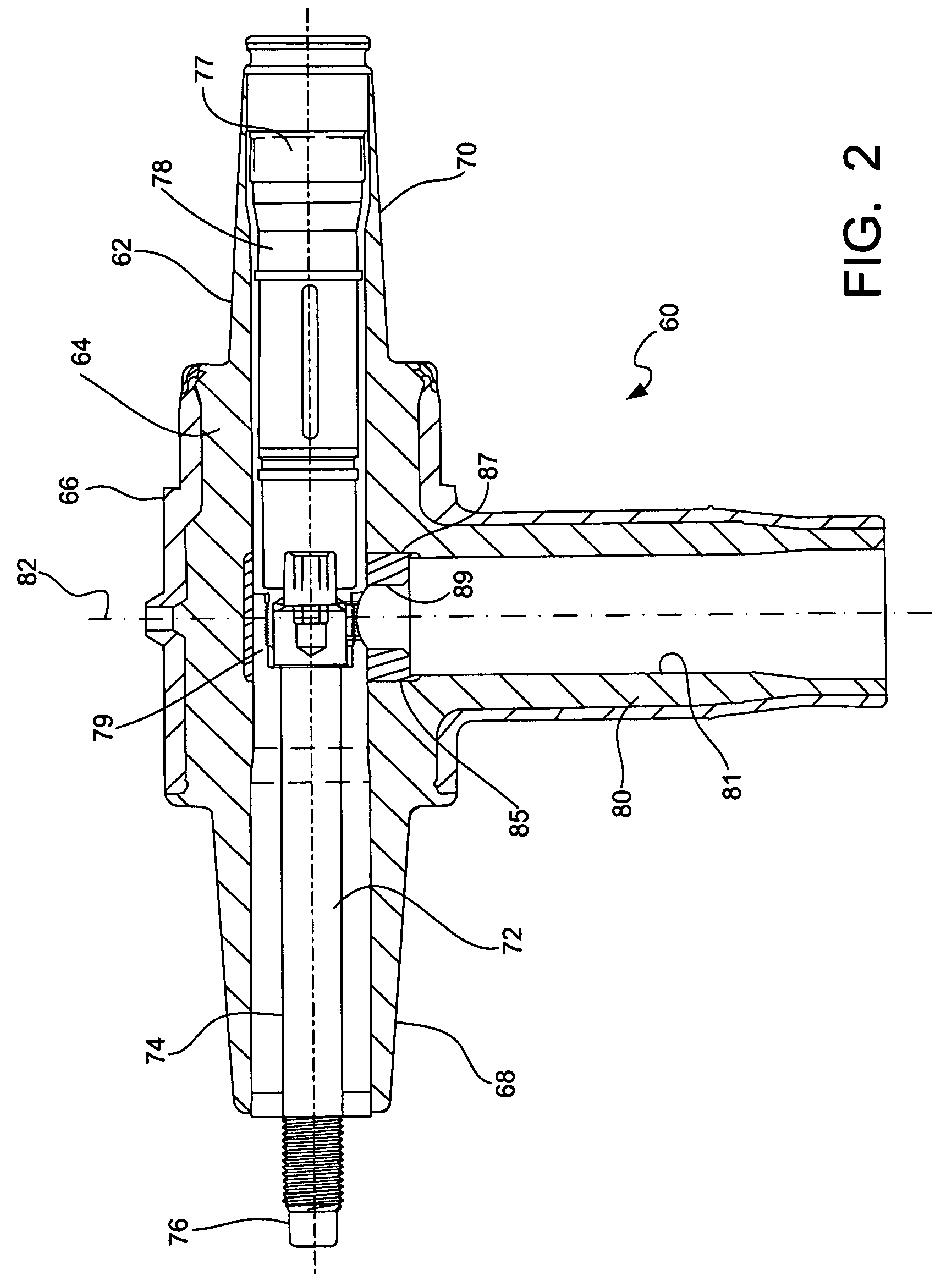
[0019]Referring first to FIG. 1, a conventional prior art connection between a medium-voltage power distribution cable 10 and a power distribution apparatus 12, such as a transformer, is shown. An apparatus bushing or terminal 14 is provided on a face of the apparatus 12 for connection with the cable 10 via an elbow T-connector 16.

[0020]The power cable elbow T-connector 16 includes a first end 18 adapted for receiving the apparatus bushing 14, a second end 20 adapted for receiving a bushing tap plug 22 opposite the first end and a third end 24 adapted for receiving the power cable 10 at the bottom of the T-connector. The opposite first and second ends 18 and 20 include a flange or elbow cuff surrounding the open receiving end thereof for sealing against a respective mating bushing 14, 22.

[0021]The loadbreak reducing tap plug 22 seated in the second end 20 of the T-connector 16 provides an electrical connection between the power cable 10 and the apparatus bushing 14, while at the sam...


PUM

PropertyMeasurementUnit
currentaaaaaaaaaa
voltageaaaaaaaaaa
voltageaaaaaaaaaa

Abstract

A separable electrical connector component generally including an insulating housing, a current carrying element disposed within the insulative housing and a voltage control device disposed within the housing. The housing has a mid-section, a first insertion end extending from the mid-section in a first direction, a second insertion end extending from the mid-section in a second direction opposite the first direction and a third section extending outwardly from the mid-section between the first and second insertion ends. The current carrying member extends through the first insertion end, the mid-section and the second insertion end. The voltage control device is disposed within the third section of the housing and is in electrical communication with the current carrying element.

Description

CROSS-REFERENCE TO RELATED APPLICATIONS[0001]This application claims the benefit of U.S. Provisional Application No. 60 / 752,644, filed on Dec. 21, 2005.FIELD OF THE INVENTION[0002]The present invention relates to electrical cable connectors, and more particularly to an electrical connector component which provides for ancillary access, such as for voltage arresting and indirect voltage sensing, while maintaining a user interface for direct voltage testing or grounding and which has standard coupling or interface structure that permits separable connection of the component to existing field installed electrical cable connectors.BACKGROUND OF THE INVENTION[0003]Connections in medium-voltage underground power distribution systems, such as between cables and transformers, are generally accomplished with specially designed separable male and female electrical connectors, such as loadbreak connectors and deadbreak connectors. Such cable connectors, used in conjunction with 15, 25 and 35 k...

Claims


Application Information

Patent Timeline
Patent Type & Authority Patents(United States)
IPC IPC(8): H01R13/53
CPCH01R13/53H01C7/12H01G4/12G01R15/16Y10S439/921H01R13/648H01R33/76
Inventor STEPNIAK, FRANK M.
Owner THOMAS & BETTS INT INC
Why Eureka
Try Eureka