
Method and apparatus for monitoring handling of a firearm

a monitoring device and firearm technology, applied in the field of firearm training devices, can solve the problems of many poor habits, high risk of accidental discharge, and injuries of police officers and civilians

Active Publication Date: 2009-03-24
ARIZONA TECH HLDG LLC
View PDF18 Cites 30 Cited by
  • Summary
  • Abstract
  • Description
  • Claims
  • Application Information

AI Technical Summary

Benefits of technology

The system effectively monitors and corrects improper firearm handling, reducing the risk of accidental discharges by providing real-time feedback and alerting relevant personnel to unsafe situations, thereby enhancing user safety and training efficacy.

Problems solved by technology

Several police officers and civilians are injured or killed by accidental discharges from firearms each year.
Although this proper placement is emphasized during firearm training, numerous poor habits may develop for several reasons.
However, the problem develops when this technique is transferred to an actual weapon that may discharge.
For example, when a police officer is utilizing a firearm to guard a suspect with the officer trigger finger placed inside the trigger guard, there is a great risk of an accidental discharge.
Moreover, poor habits may be developed on a shooting range.
These actions result in an incorrect technique since the trigger finger should only enter the trigger guard when the shooter is ready to shoot.
In addition, a firearm user may intentionally or unintentionally position their hand or finger into the firearm trigger guard.
This action produces a situation containing high physical risk to the user and bystanders since discharge of the firearm is likely.
However, the risk is often unapparent to those affected, or unknown to others that may be able to lend assistance to diffuse the situation (e.g., law enforcement officers in the field, police dispatch, military, etc.).

Method used


Image

  • Method and apparatus for monitoring handling of a firearm
  • Method and apparatus for monitoring handling of a firearm
  • Method and apparatus for monitoring handling of a firearm

Examples


Embodiment Construction

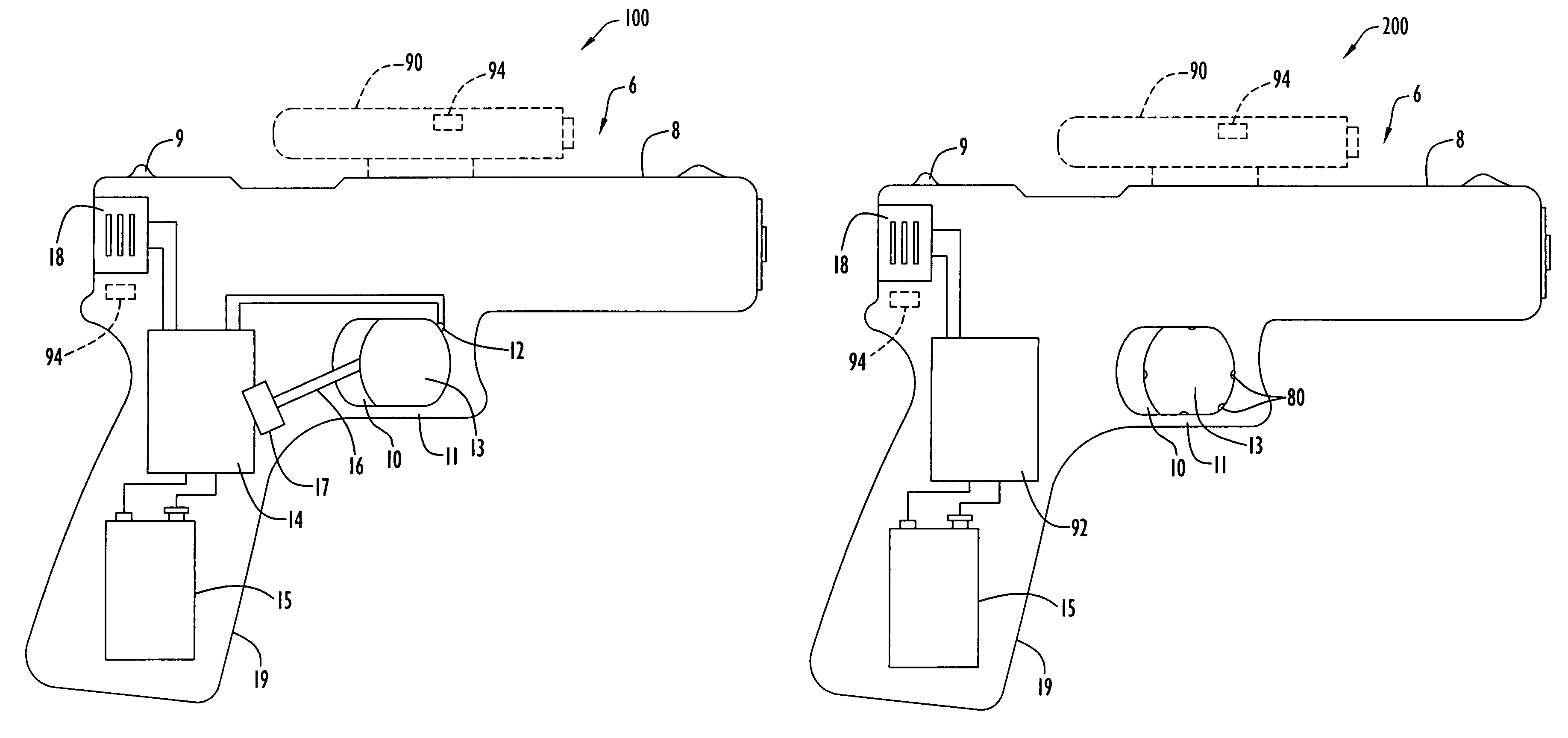
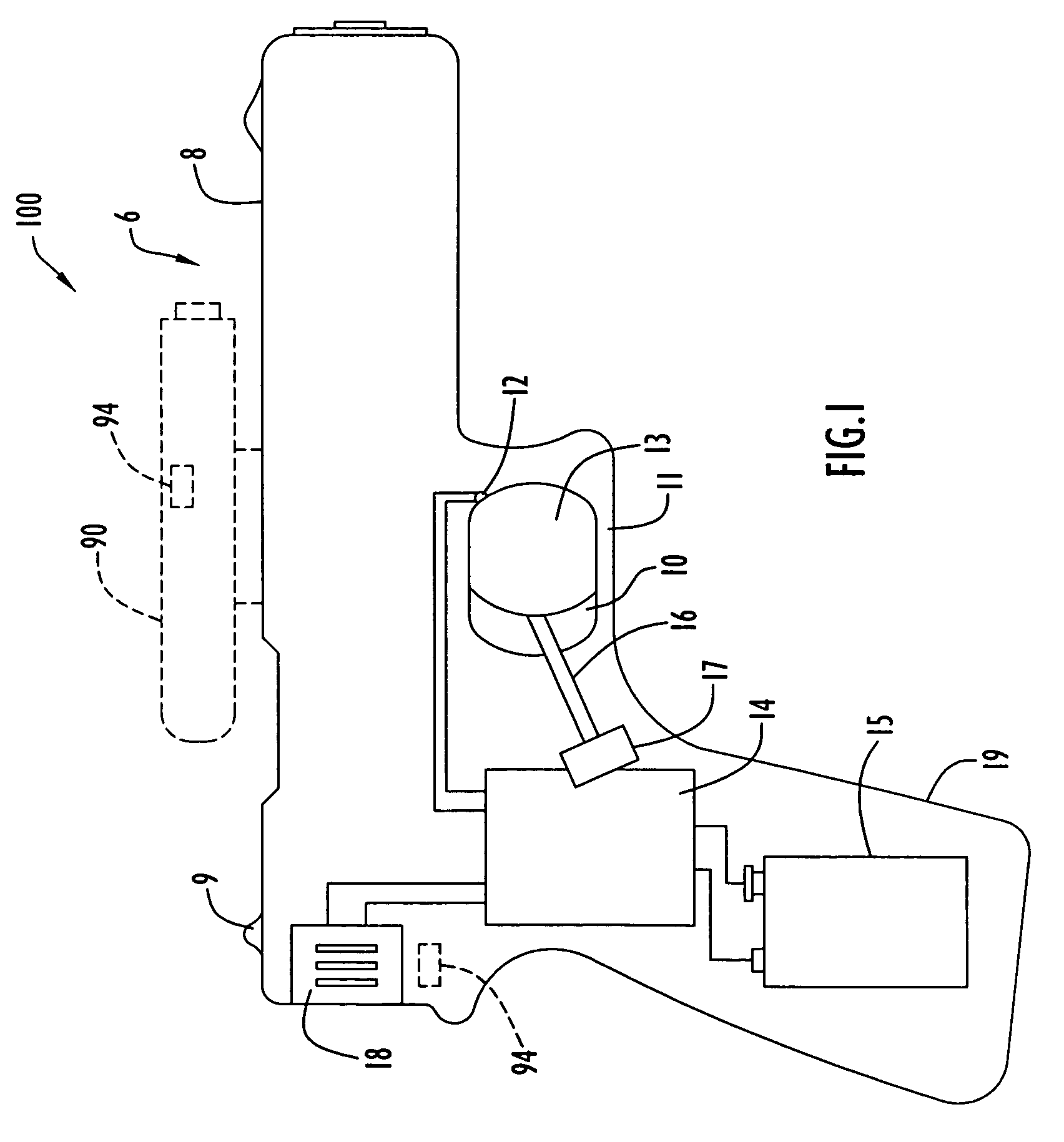
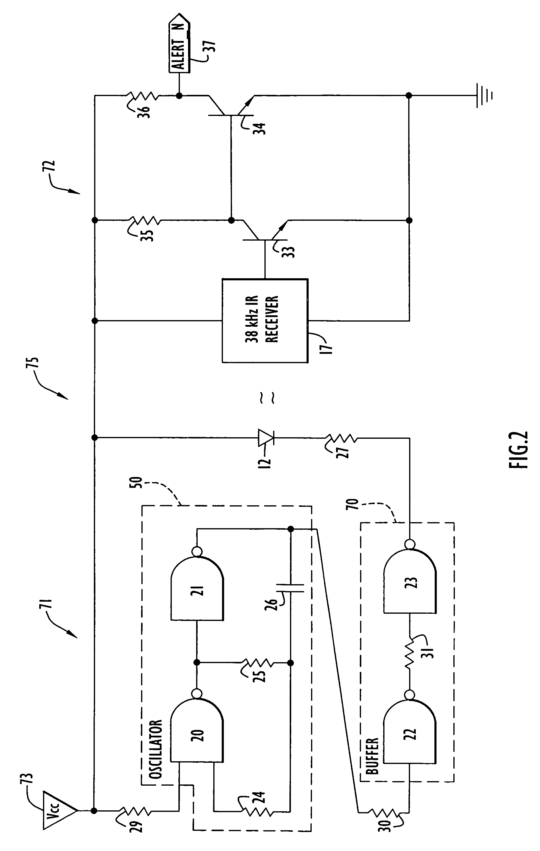
[0025]An exemplary firearm employing a firearm monitoring system according to the present invention is illustrated in FIG. 1. The firearm monitoring system senses the position of a user hand or trigger finger and produces an alarm in response to detecting the trigger finger in the proximity of the trigger. In the case of a training application or embodiment, the monitoring system produces an alarm in response to detecting incorrect handling of the firearm (e.g., incorrect position of the user hand or trigger finger relative to the firearm trigger). When employed with an actual firearm, the monitoring system may alternatively transmit a warning message in response to detection of the user hand or trigger finger near the firearm trigger to notify personnel associated with the user (e.g., law enforcement, military, etc.) that the user is in a situation likely to result in discharge of the user firearm (e.g., accidental discharge when the user hand or finger placement is unintentional, ...


PUM


Abstract

A firearm monitoring system according to the present invention senses the position of a user hand or trigger finger on a weapon and generates a warning, notification, status or control signal when the user finger position is proximate the trigger. One embodiment generates and conditions an excitation stimulus (e.g., interrupted by the presence of a trigger actuator), drives a sensor with that stimulus, detects the user finger position through a change in the sensor output, and generates an appropriate signal for a downstream warning or other device (e.g., alarm, radio unit, laser sighting system, etc.). In this embodiment, the sensor may detect the presence of an object or finger penetrating a trigger guard plane. Another embodiment utilizes a set of sensors to detect the placement of a user trigger finger relative to the trigger. In addition, various types of output alarms may be utilized (e.g., visual and audio alarms, etc.).

Description

BACKGROUND OF THE INVENTION[0001]1. Technical Field[0002]The present invention pertains to firearms and firearm training devices. In particular, the present invention pertains to a firearm monitoring device that senses the position of a user hand or trigger finger relative to the firearm trigger. In the case of a training application or embodiment, the monitoring device produces an alarm in response to detecting incorrect handling of the firearm (e.g., incorrect position of the user hand or trigger finger relative to the firearm trigger). When employed with an actual firearm, the monitoring device may alternatively transmit a warning message in response to detection of the user hand or trigger finger near the firearm trigger to notify personnel associated with the user (e.g., law enforcement, military, etc.) that the user is in a situation likely to result in discharge of the user firearm (e.g., accidental discharge when the user hand or finger placement is unintentional, combat, sh...

Claims


Application Information

Patent Timeline
Patent Type & Authority Patents(United States)
IPC IPC(8): F41A17/46F41A17/00
CPCF41A17/06F41A33/00
Inventor FARRELL, MICHAEL ANTHONYBRABANDT, CALIN WILLIAM
Owner ARIZONA TECH HLDG LLC
Learn More