
Automotive coolant control valve

a technology for controlling valves and coolants, applied in the direction of valve operating means/release devices, machines/engines, transportation and packaging, etc., can solve the problems of increasing the overall cost of the multiple heater system, increasing system costs, and sacrificing the ability to independently. , to achieve the effect of simplifying the plumbing and packaging, and reducing the cost of the system

Active Publication Date: 2009-03-24
ROBERTSHAW US HLDG
View PDF3 Cites 36 Cited by
  • Summary
  • Abstract
  • Description
  • Claims
  • Application Information

AI Technical Summary

Benefits of technology

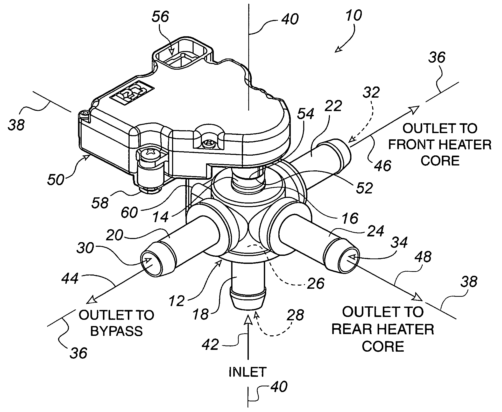
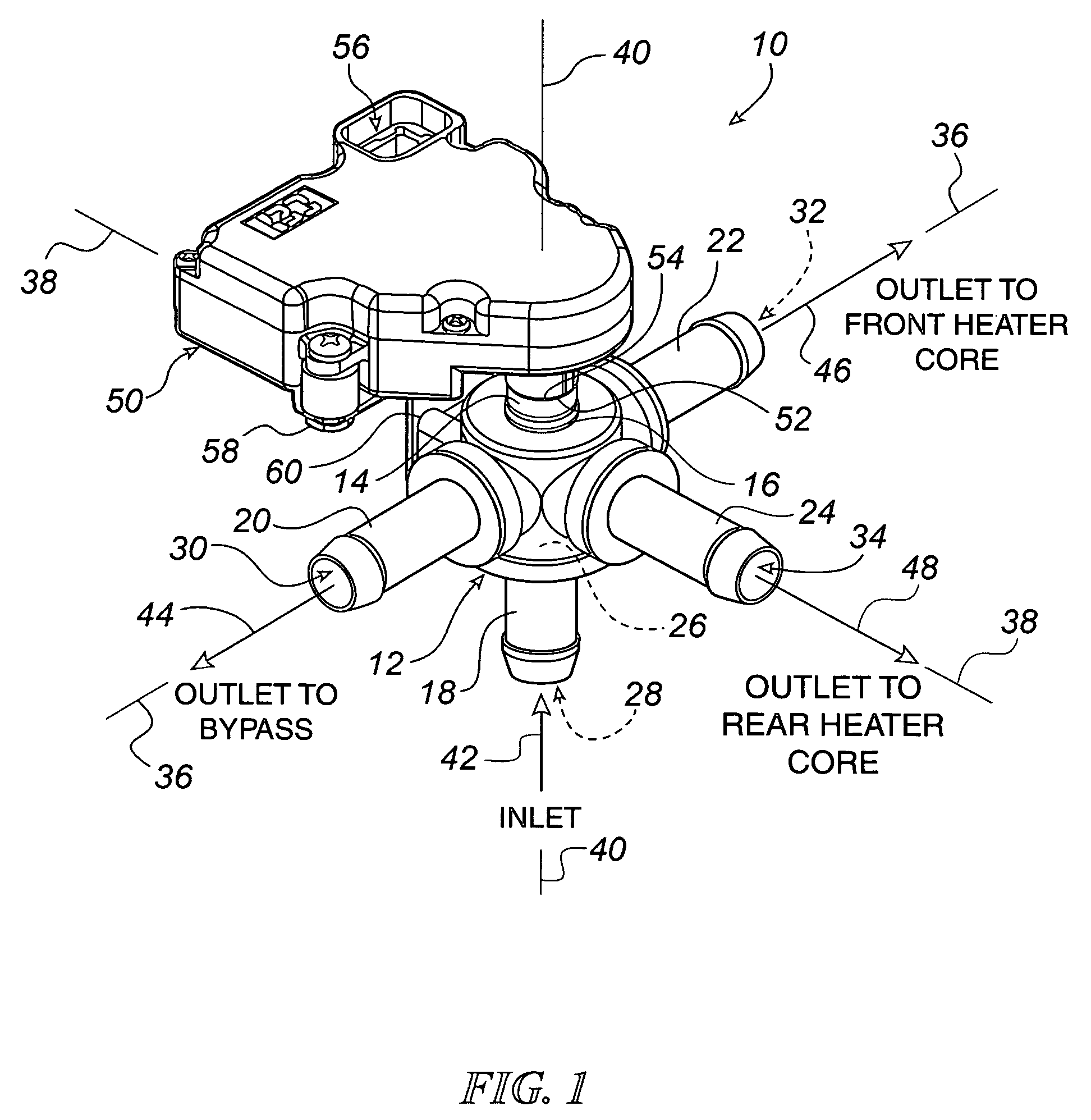
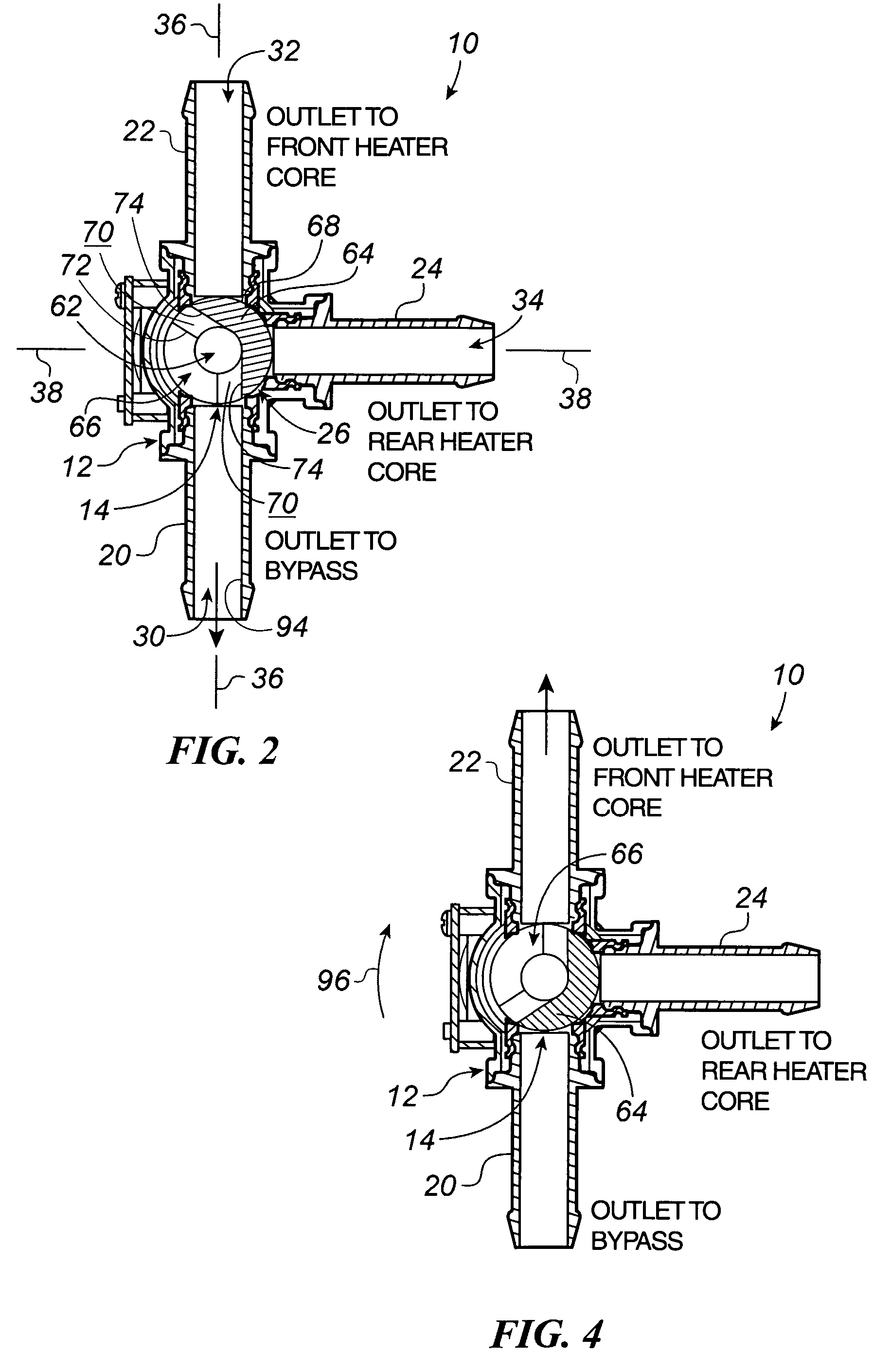
[0009]The invention provides a flow control valve that simplifies the plumbing and packaging of a multiple heater system without sacrificing the ability to independently control the individual heaters. To accomplish this task, the flow control valve uses a rotatable cylinder as a passageway and as a coolant directing device. By incorporating a bypass outlet into its overall design, the flow control valve also permits continuous circulation of the coolant even when heat in a passenger compartment of a vehicle is not called for or turned off. Moreover, the heated coolant is not undesirably carried into the passenger compartment of the vehicle such that the heater cores are allowed to radiate heat on warm and hot days.
[0010]In one embodiment of the present invention, the flow control valve includes four ports, i.e. one inlet port, a front heater outlet port, a rear heater outlet port and a bypass port. Control of fluid flow through the various ports of the flow control valve is provided by an actuator that controls the positioning of a flow directing cylinder positioned between the inlet port and the outlet ports. Positioning of the cylinder allows for full bypass operation, full front heater operation, proportional front and rear heater operation, and combinations thereof.

Problems solved by technology

Unfortunately, each control valve, actuator used to manipulate the control valve, tree, connecting device, length of tubing connecting the various components together, and like heater components increases the overall cost of the multiple heater system.
In addition, each of the components is subject to wear, failure, and / or leakage and, consequently, replacement.
Having to replace worn, failed, or leaking components is a time consuming endeavor and will also increased system costs.
Therefore, multiple heater systems with a large number of components are disfavored.

Method used


Image

  • Automotive coolant control valve
  • Automotive coolant control valve
  • Automotive coolant control valve

Examples


Embodiment Construction

[0021]Referring to FIG. 1, an embodiment of a flow control valve 10 for selectively routing a fluid constructed in accordance with the teachings of the present invention is illustrated. In an exemplary embodiment for use in an automotive heating system, the fluid is an engine coolant, although in other applications a hydraulic fluid or other types of fluid may be controlled thereby. However, while the present invention may be well suited in various applications, the following description will utilize the exemplary environment of a dual zone heater application in the automotive industry. Those skilled in the art, however, will recognize that such description is provided by way of example only, and not by way of limitation.

[0022]The flow control valve 10 comprises a housing 12 and a rotatable cylinder 14. The housing 12 may be formed from a variety of suitable materials such as, plastic, steel, and the like, depending on the particular application or environment in which the flow cont...


PUM


Abstract

A flow control valve for selectively routing a coolant in a dual-zone heater system is provided. The flow control valve includes a housing and a flow control device. The housing includes an inlet port, a bypass outlet, a front heater outlet, and a rear heater outlet communicating through an internal cavity. The flow control device, which can be a cylinder, sphere, etc., is rotatably positioned in the internal cavity. The flow control device has an axial channel and generally radial aperture. The axial channel transports the coolant received from the inlet port through the flow control device, and the aperture delivers the coolant to one or more of the bypass outlet, the front heater outlet, and the rear heater outlet as the flow control device is rotated. In this way the circuit is not deadheaded.

Description

FIELD OF THE INVENTION[0001]The present invention generally relates to automotive heating systems and, in particular, to a control valve for controlling coolant within an automotive heating system.BACKGROUND OF THE INVENTION[0002]A conventional automobile includes a heater (i.e., heating system) configured to selectively introduce warm air into a passenger compartment. As the warm air is circulated throughout the passenger compartment, the temperature within the passenger compartment is elevated to within a desired temperature range. Therefore, the occupants seated in passenger compartment of the automobile are kept comfortable.[0003]The typical heater noted above includes, among other things, a control valve, a heater core, and a fan. The flow of heated coolant to the heater core is generally directed through flexible tubing or some other type of conduit. This heater loop is typically coupled in parallel to the radiator loop of the vehicle. As the engine is operated, the temperatur...

Claims


Application Information

Patent Timeline
Patent Type & Authority Patents(United States)
IPC IPC(8): F16K11/074F01P7/02F16K11/07F16K11/078F16K31/02
CPCB60H1/00485B60H1/00885B60H2001/00942F01P2060/08F16K11/0876Y10T137/86549Y10T137/86831Y10T137/86863
Inventor NORRIS, ROBERTMCLANE, R. ALLAN
Owner ROBERTSHAW US HLDG
Learn More