Quickly activatable structure of gas sensor element

a technology of gas sensor element and rapid activation, which is applied in the direction of instruments, material electrochemical variables, measurement devices, etc., can solve the problems of difficulty in entering gas from outside the gas sensor element into the measurement gas chamber, and achieve the effect of reducing the amount of gas staying, sacrificing the ability of diffusion resistor, and quickly activating

Active Publication Date: 2009-03-17
DENSO CORP
View PDF11 Cites 0 Cited by
  • Summary
  • Abstract
  • Description
  • Claims
  • Application Information

AI Technical Summary

Benefits of technology

[0026]It is another object of the present invention to provide an improved structure of a laminated gas sensor element capable of being activated quickly and minimizing an output error during a transition of activation thereof.
[0028]An output error of a gas sensor element of the above type arises, as discussed in the introductory part of this application from the fact that expansion of gas staying in the measurement gas chamber by rapid heating of the gas sensor element is disturbed by the diffusion resistor during a transition of activation of the sensor element, thereby resulting in a difficulty in entrance of gas from outside the gas sensor element into the measurement gas chamber. In order to avoid this, the gas sensor element of the invention is designed to have the measurement gas chamber whose volume is 0.15 mm3 or less, thereby decreasing the amount of the gas staying within the measurement gas chamber without sacrificing the ability of the diffusion resistor. Specifically, the gas sensor element is capable of expelling the gas outside the measurement gas chamber before completion of activation of the gas sensor element, thereby permitting the gas sensor element to be activated quickly and minimizing an output error during a transition of the activation.

Problems solved by technology

An output error of a gas sensor element of the above type arises, as discussed in the introductory part of this application from the fact that expansion of gas staying in the measurement gas chamber by rapid heating of the gas sensor element is disturbed by the diffusion resistor during a transition of activation of the sensor element, thereby resulting in a difficulty in entrance of gas from outside the gas sensor element into the measurement gas chamber.

Method used


Image

  • Quickly activatable structure of gas sensor element
  • Quickly activatable structure of gas sensor element
  • Quickly activatable structure of gas sensor element

Examples


first embodiment

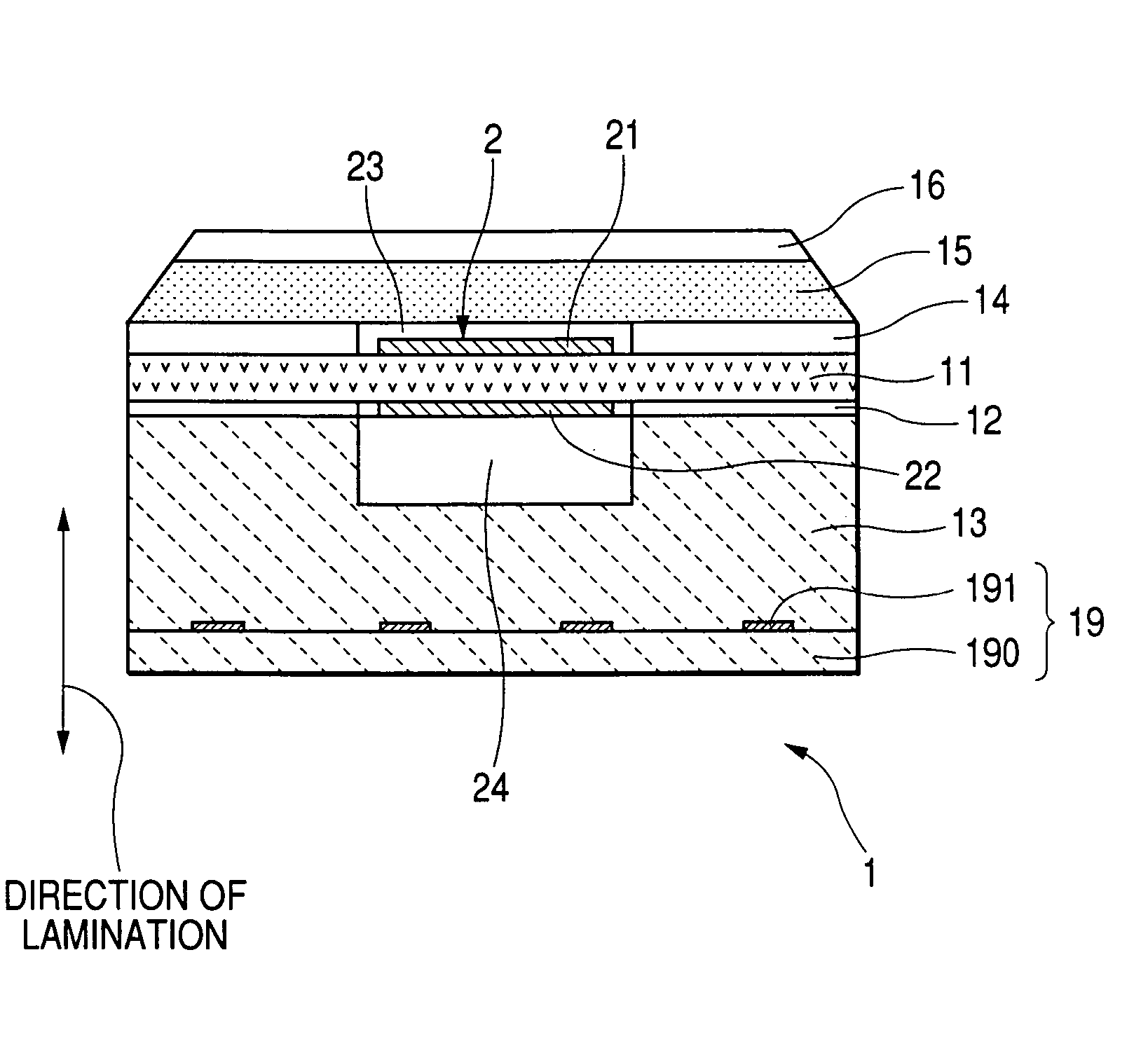
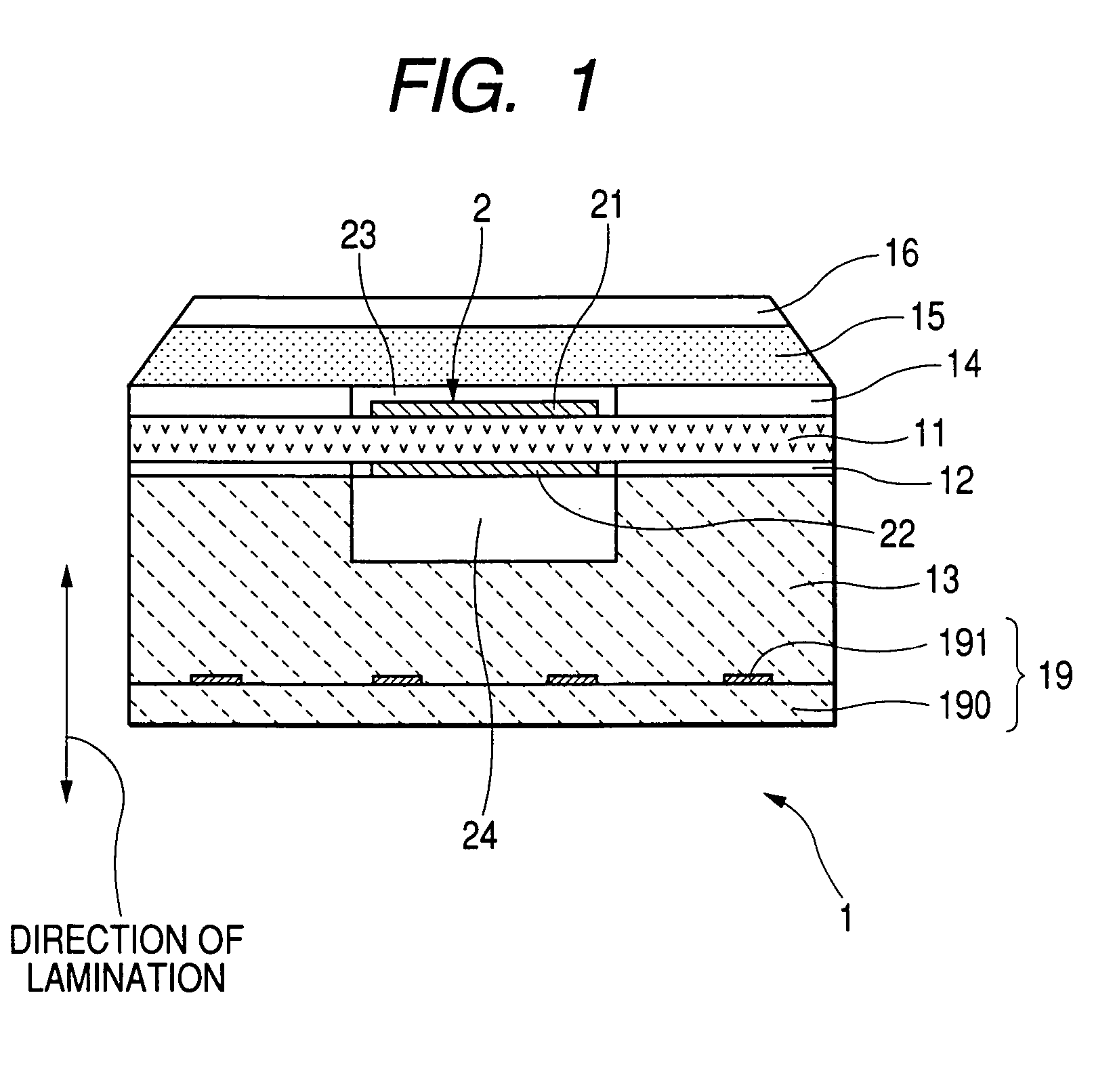
[0048]Referring now to the drawings, wherein like numbers refer to like parts in several views, particularly to FIGS. 1, 2 and 3, there is shown a gas sensor element 1 according to the invention. The gas sensor element 1 is to be incorporated within a body of a gas sensor which may be installed in an exhaust pipe of an automotive engine to measure the concentration of oxygen (O2) contained in exhaust gasses of the engine in order to determine an air-fuel (A / F) ratio of a mixture supplied to combustion chambers of the engine for use in an exhaust emission feedback control system for controlling the combustion of the engine. An overall structure of such a gas sensor is not essential for this invention, and explanation thereof in detail will be omitted here.

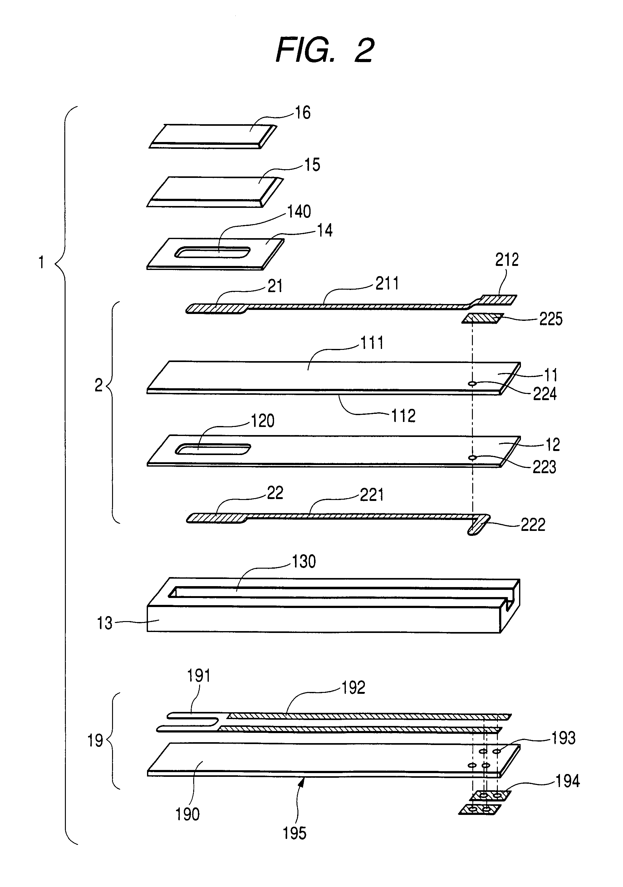
[0049]The gas sensor element 1 is made of a laminate of a heater 19, a spacer 13, an insulating layer 12, an oxygen ion-conductive solid electrolyte layer 11, a spacer 14, a diffusion resistance layer 15, and a dense layer 16.

[0050]...

second embodiment

[0087]FIG. 12 shows a gas sensor element 3 according to the invention which has a two-cell structure and made of a laminate of solid electrolyte layers 31 and 34, spacers 32 and 35, an insulating layer 36, and a heater substrate 37.

[0088]The gas sensor element 3 has a measurement gas chamber 320 surrounded by the solid electrolyte layers 31 and 34 and the spacer 32. The measurement gas enters the measurement gas chamber 320 through a hole 310 extending through the solid electrolyte layer 31 and a porous layer 33. The porous layer 33 is interposed between the solid electrolyte layers 31 and 34 and works as a diffusion resistor. The gas sensor element 3 also has a reference gas chamber 350 surrounded by the solid electrolyte layer 34, the spacer 35, and the insulating layer 36.

[0089]The gas sensor element 3 also includes a first electrochemical cell 41 and a second electrochemical cell 42. The first electrochemical cell 41 is made up of the solid electrolyte layer 31 and a pair of ele...

third embodiment

[0094]FIG. 13 shows a gas sensor element 5 according to the invention which is of a two-cell type and has a separate heater 502.

[0095]The gas sensor element 5 consists essentially of an element body 501 and the heater 502 facing the element body 501 through a clearance 500. The element body 501 is made up of solid electrolyte layers 51 and 53 and a porous material-made spacer 52. The heater 502 is made up of an insulating layer 54 and a heater substrate 55 on which a heater element 550 is fabricated.

[0096]The element body 501 has a measurement gas chamber 520 defined by the solid electrolyte layers 51 and 53 and the spacer 52. The element body 501 also includes a first electrochemical cell 43 and a second electrochemical cell 44. The first electrochemical cell 43 includes an electrode 431 embedded in the solid electrolyte layer 51 and an electrode 432 exposed to the measurement gas chamber 520. The second electrochemical cell 44 is made up of the solid electrolyte layer 53 and a pai...


PUM

PropertyMeasurementUnit
volumeaaaaaaaaaa
heightaaaaaaaaaa
heightaaaaaaaaaa

Abstract

A gas sensor element which may be employed in measuring the concentration of gas such O2 is provided. The gas sensor element is of a laminated type and designed to introduce gas to be measured into a measurement gas chamber through a diffusion resistor. The measurement gas chamber has a volume of 0.15 mm3 in order to facilitate expelling of the gas remaining within the measurement gas chamber during transition of thermal activation of the gas sensor element.

Description

BACKGROUND OF THE INVENTION[0001]1. Technical Field of the Invention[0002]The present invention relates generally to an improved structure of a gas sensor element which is quickly activatable without sacrificing output characteristics thereof which may be built in a gas sensor employed in combustion control for automotive internal combustion engines.[0003]2. Background Art[0004]There are known exhaust emission feedback control systems which have an air-fuel ratio (A / F) sensor installed in an exhaust pipe of an automotive engine to measure the concentration of oxygen (O2) contained in exhaust emissions and determine an air-fuel ratio in the engine as a function of the measured value for controlling combustion of the engine.[0005]Particularly, when a three-way catalyst is used to convert air pollutants contained in exhaust emissions of automotive engines into harmless products, it is essential to control combustion of the engine so as to keep an air-fuel ratio of a mixture supplied to...

Claims


Application Information

Patent Timeline
Patent Type & Authority Patents(United States)
IPC IPC(8): G01N27/41G01N27/26G01N27/407G01N27/409G01N27/419
CPCG01N27/4071
Inventor NAITO, SUSUMUNAKAE, MAKOTOIMAMURA, SHINICHIRO
Owner DENSO CORP
Why Eureka
Try Eureka