Structure of an extendable pull handle for luggage

Inactive Publication Date: 2009-03-24
CHEN SHOU MAO
View PDF4 Cites 5 Cited by
  • Summary
  • Abstract
  • Description
  • Claims
  • Application Information

AI Technical Summary

Benefits of technology

[0007]1. The present invention uses the new features of the first and second snapper 4050, and the separation of the guide slide plate 52 of the second snapper and the connection between the limit column 44 and the pointing slot 53; with the coordination

Problems solved by technology

Since the so-called fixation column generally takes flexible components as its braking elements, mutual interference of acting force will likely occur in the case of two flexible components.
This will lead t

Method used


Image

  • Structure of an extendable pull handle for luggage
  • Structure of an extendable pull handle for luggage
  • Structure of an extendable pull handle for luggage

Examples


Example

[0017]The features and the advantages of the present invention will be more readily understood upon a thoughtful deliberation of the following detailed description of a preferred embodiment of the present invention with reference to the accompanying drawings.

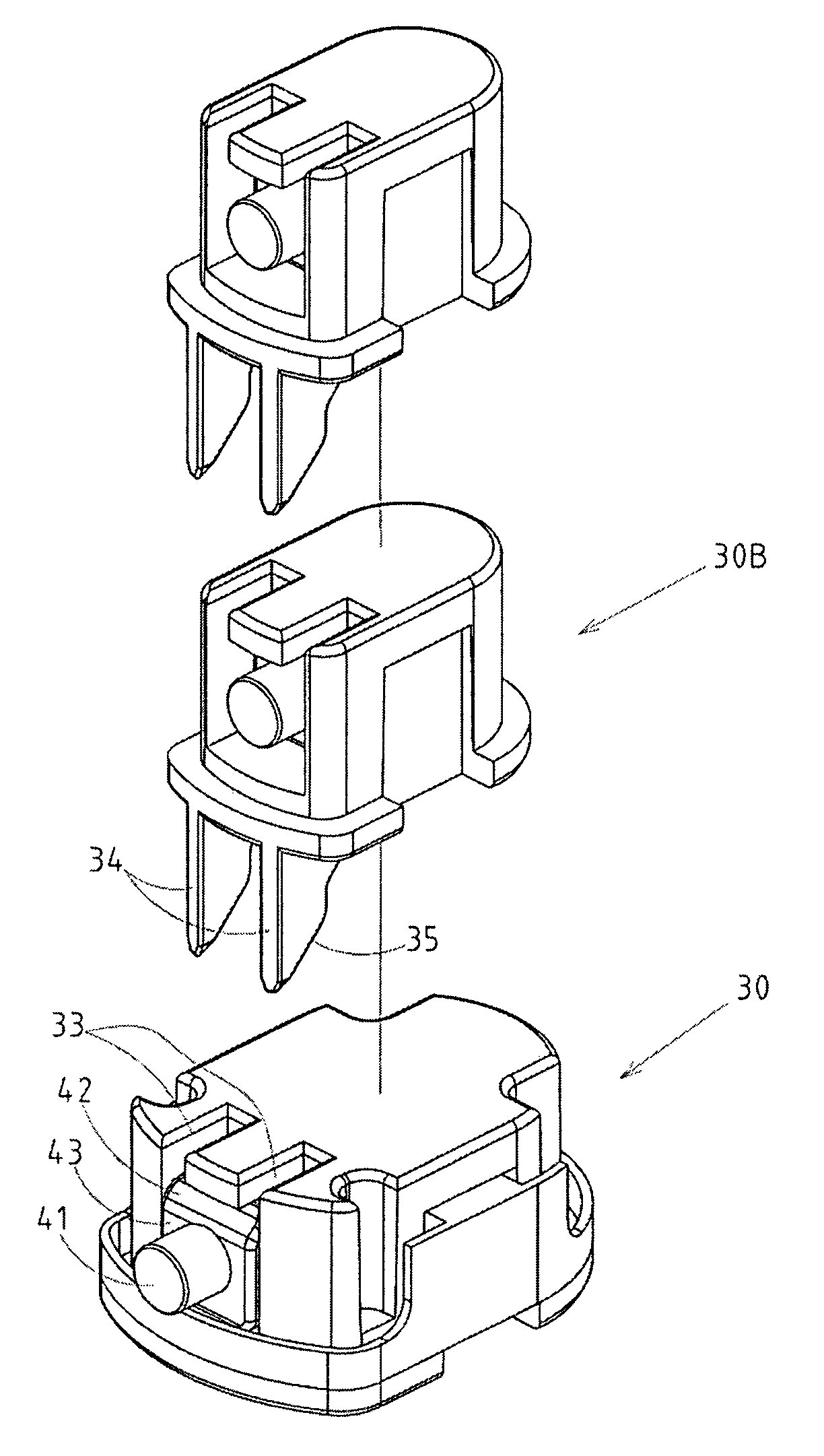
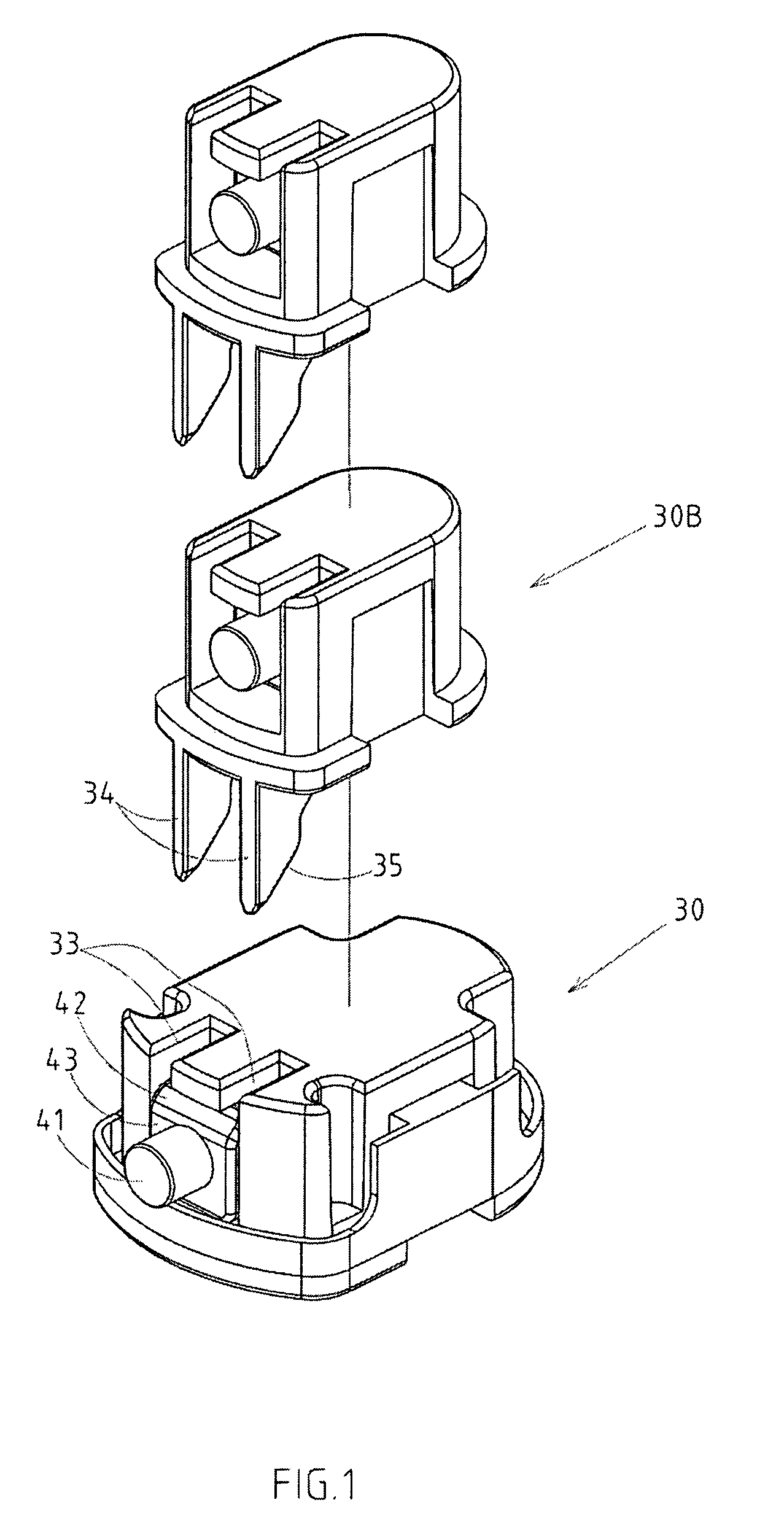
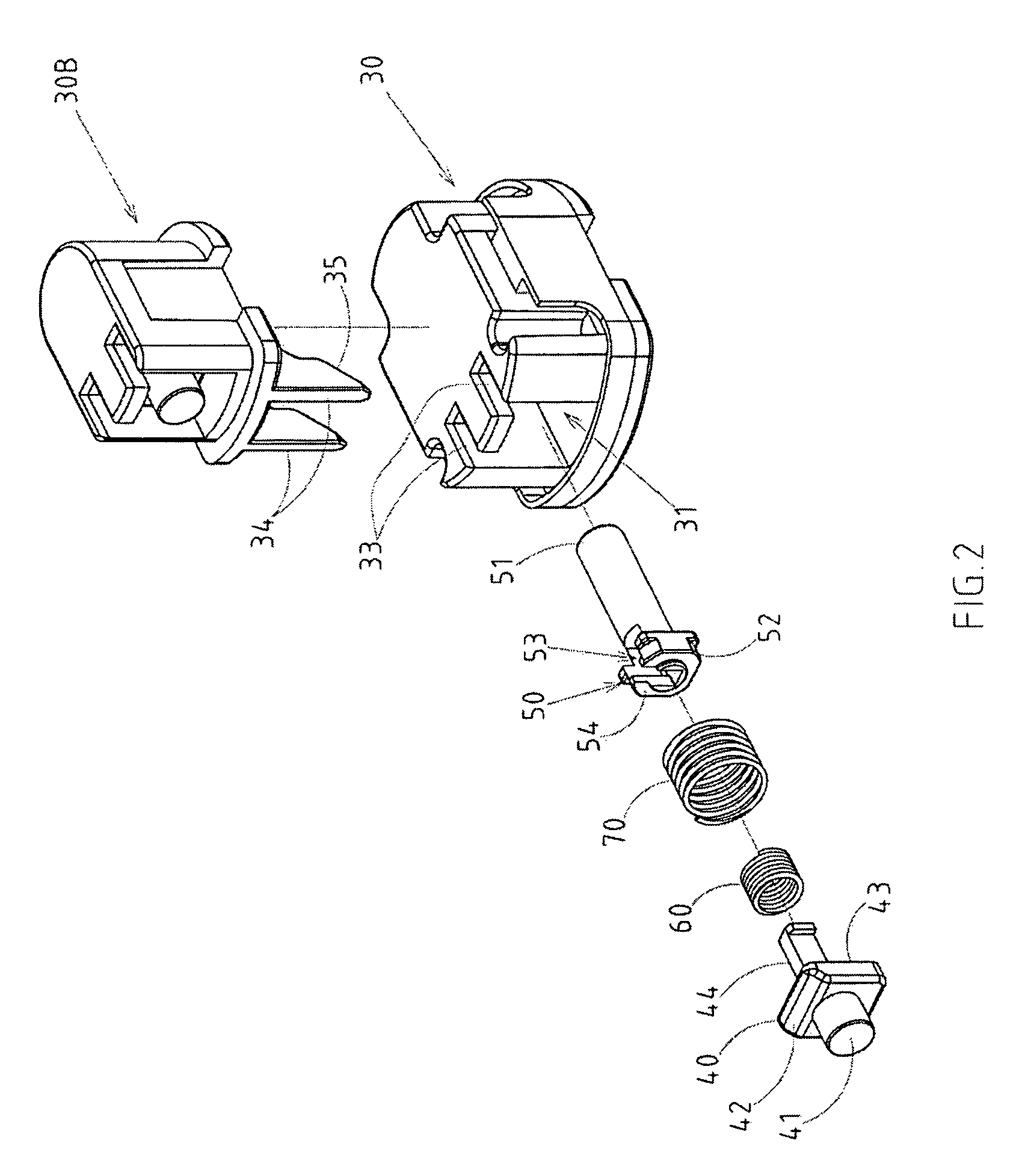
[0018]As shown in FIGS. 1-4, there is an extendable pull handle for luggage embodied in the present invention.

[0019]The invention includes a pull handle A, which is formed by several hollow tubes through internal and external pin joints. The base frame 30 of hollow tubes 1020 is provided with an actuating slot 31, wherein some fixation members are placed; at both sides of hollow tube 20 facing externally there are separately provided with an upper fixation hole 21 and a lower fixation hole 22. As the said hollow tube 10 is extended, it can be locked onto upper fixation hole 21 of external hollow tube 20 via the fixation member; as the said hollow tube 10 is contracted, it can be locked onto lower fixation hole 22 of external hol...


PUM


Abstract

The extendable pull handle for luggage includes several hollow tubes, and the fixed components are placed at the base frame of the hollow tubes of the pull handle. At both sides of hollow tube facing externally, there are separately provided with an upper fixation hole and a lower fixation hole. The component set includes two sets of snapper and a big and small springs; the exterior of first snapper is fitted with the first protruding column, which is protruded and locked onto upper fixation hole of external hollow tube. And, an oblique guide plane is provided at the middle top of first snapper, and a concave surface, at which center and protruded inward is a limit column; the exterior of the second snapper is fitted with a second protruding column, which is protruded and locked onto upper fixation hole of external hollow tube.

Description

RELATED U.S. APPLICATIONS[0001]Not applicable.STATEMENT REGARDING FEDERALLY SPONSORED RESEARCH OR DEVELOPMENT [0002]Not applicable.REFERENCE TO MICROFICHE APPENDIX[0003]Not applicable.FIELD OF THE INVENTION [0004]The present invention relates generally to luggage, and more particularly to an innovative luggage designed with an extendable pull handle.BACKGROUND OF THE INVENTION [0005]The conventional pull handles of luggage are designed with a flexible structure, whereby the users can adjust them if necessary. The present invention is intended to improve a flexible structure for a wide array of pull handles of luggage, which lacks of smoothness and accuracy for locking and release of fixation columns (knobs), in despite of continuous development and innovation efforts by relevant operators in this industry. Since the so-called fixation column generally takes flexible components as its braking elements, mutual interference of acting force will likely occur in the case of two flexible ...

Claims


Application Information

Patent Timeline
IPC IPC(8): B65D13/00
CPCA45C13/262Y10T16/451
Inventor CHEN, SHOU MAO
Owner CHEN SHOU MAO
Why Eureka
Try Eureka