

Mounting system for a vertical conveyor belt
a technology of conveyor belts and mounting systems, which is applied in the direction of conveyor parts, mechanical conveyors, transportation and packaging, etc., can solve the problems of increasing the frictional heating of the belt, increasing the power of the belt to drive the belt, and increasing the tension applied to the vertical conveyor belt. , to achieve the effect of increasing the tension, reducing the time to alter the tension, and increasing the tension supplied
- Summary
- Abstract
- Description
- Claims
- Application Information
AI Technical Summary
Benefits of technology
Problems solved by technology
Method used
Image

Examples
Embodiment Construction
[0040]Although the disclosure hereof is detailed to enable those skilled in the art to practice the invention, the embodiments published herein merely exemplify the present invention.
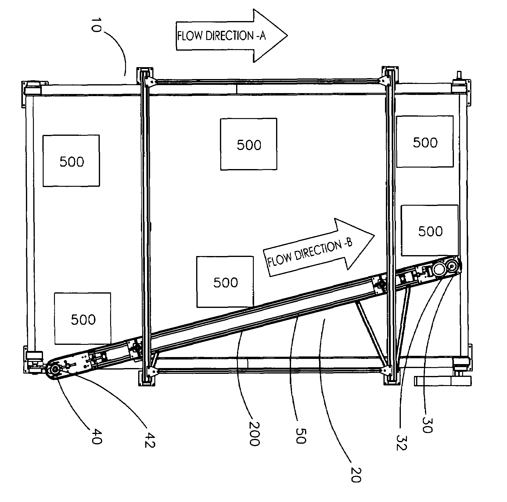
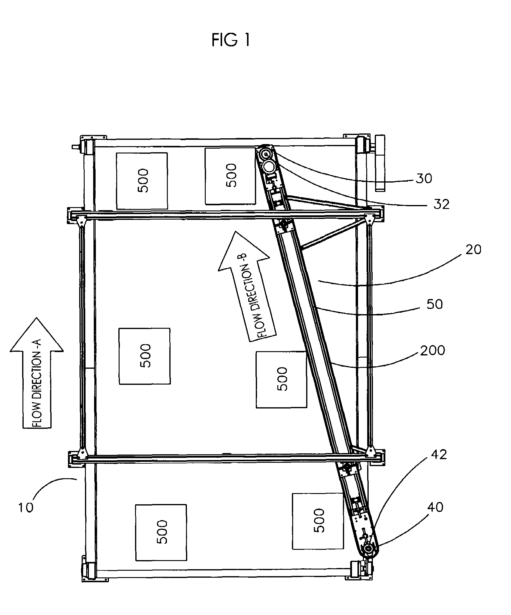
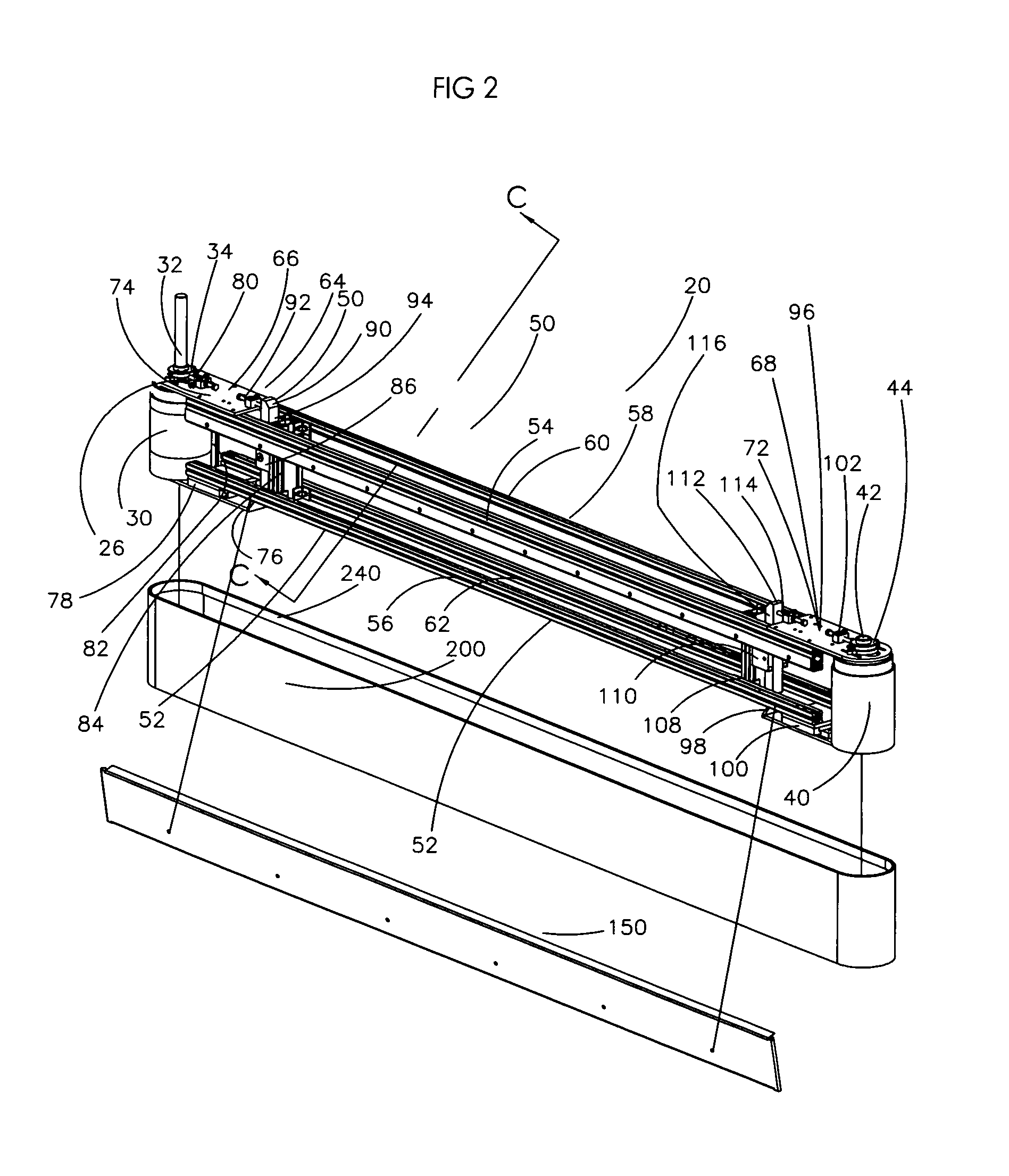
[0041]In the most general sense, the present invention is a diverter. More specifically, the current invention is an endless vertical conveyor belt mounted about a frame that can be used to divert one or more items from a first carriage path to a second carriage path. Within the scope of the present invention, a continuous upper coupling member or rider is attached to the inward side of the endless conveyor belt and reciprocates with the first and second coupling members mounted to the frame. The combination of the coupling members, a drive pulley and follower roll allow the endless vertical conveyor belt to traverse about the conveyor frame and divert one or more items from a first carriage path to a second carriage path. It has been unexpectedly discovered that certain embodiments of the present diver...
PUM
 Abstract
Description
Claims
Application Information